Thank you for visiting nature.com. You are using a browser version with limited support for CSS. To obtain the best experience, we recommend you use a more up to date browser (or turn off compatibility mode in Internet Explorer). In the meantime, to ensure continued support, we are displaying the site without styles and JavaScript.
- View all journals
- My Account Login
- Explore content
- About the journal
- Publish with us
- Sign up for alerts
- Open access
- Published: 01 February 2023

Efficient dispersion modeling in optical multimode fiber
- Szu-Yu Lee ORCID: orcid.org/0000-0002-9381-3849 1 , 2 ,
- Vicente J. Parot ORCID: orcid.org/0000-0002-9261-6667 1 , 3 ,
- Brett E. Bouma 1 , 2 , 4 &
- Martin Villiger ORCID: orcid.org/0000-0003-3819-1271 1
Light: Science & Applications volume 12 , Article number: 31 ( 2023 ) Cite this article
4108 Accesses
3 Citations
23 Altmetric
Metrics details
- Biophotonics
- Fibre optics and optical communications
- Imaging and sensing
Dispersion remains an enduring challenge for the characterization of wavelength-dependent transmission through optical multimode fiber (MMF). Beyond a small spectral correlation width, a change in wavelength elicits a seemingly independent distribution of the transmitted field. Here we report on a parametric dispersion model that describes mode mixing in MMF as an exponential map and extends the concept of principal modes to describe the fiber’s spectrally resolved transmission matrix (TM). We present computational methods to fit the model to measurements at only a few, judiciously selected, discrete wavelengths. We validate the model in various MMF and demonstrate an accurate estimation of the full TM across a broad spectral bandwidth, approaching the bandwidth of the best-performing principal modes, and exceeding the original spectral correlation width by more than two orders of magnitude. The model allows us to conveniently study the spectral behavior of principal modes, and obviates the need for dense spectral measurements, enabling highly efficient reconstruction of the multispectral TM of MMF.
Pattern formation by turbulent cascades
Xander M. de Wit, Michel Fruchart, … Vincenzo Vitelli

Parametrically driven pure-Kerr temporal solitons in a chip-integrated microcavity
Grégory Moille, Miriam Leonhardt, … Miro Erkintalo

Integrated optical frequency division for microwave and mmWave generation
Shuman Sun, Beichen Wang, … Xu Yi
Introduction
Managing and controlling optical scattering in complex or disordered media has enabled vast new possibilities for imaging, sensing, and manipulation in optical engineering and physics, including communications 1 , 2 , biomedical optics 3 , 4 , 5 , 6 , defense 7 , mesoscopic physics 8 , and quantum optics 9 . Close attention has been paid to calibration methods for compensating the seemingly chaotic transmission through complex media at single wavelengths 3 , 10 , 11 . Dispersion, due to geometric effects as well as material properties, inflicts additional spectral scrambling and remains a pervasive and significant technical impediment for multi-color or broadband applications in complex media 3 . Light transport through complex media results in independent intensity distributions beyond a narrow spectral correlation range 12 , 13 , to the advantage of spectrometry 14 , 15 , but requiring independent calibration at many frequencies for accurate multispectral wave-control 16 , 17 , 18 . Inconveniently, this results in burdensome measurement time and data storage, which scale linearly with spectral bandwidth and resolution-determined sampling rate 16 .
Optical multimode fiber (MMF) has emerged as an ideal tool for studying transmission through complex media attributed to its high throughput with low loss, defined degrees of freedom, small form factor, controllable geometry, and remarkable dispersion 2 , 14 , 19 , 20 , 21 , 22 , 23 . Principal modes (PMs), the eigenmodes of the group-delay operator, define pairs of specific input and output mode patterns that are unaffected by a change in wavelength 1 , 24 , 25 . PMs transmit pulses with a characteristic delay free of temporal scattering into a defined spatial output pattern. Yet, the superposition of PMs that generalizes to an arbitrary input pattern results in a chaotic output that is very sensitive to a change in wavelength. The chromato-axial memory effect has been shown to link a spectral shift of the input illumination with an axial homothetic dilation of the output speckle pattern 26 . Whether this effect is applicable to all available spatial channels stands to be investigated, but attests to a highly deterministic wavelength-dependence of the MMF transmission matrix (TM). Many practical applications require accurate spatio-spectral control and knowledge of the full, spectrally resolved TM. Improved understanding of dispersion and mode mixing in MMF remains an imperative step towards efficient calibration of multispectral TMs (msTMs) and enabling applications associated with multispectral and broadband light transport through MMF.
Here we establish a parametric dispersion model of the optical transmission through MMF. It develops the difference between the TMs at two frequencies as an exponential map, polynomial in the frequency offset. This is inspired by the well-known polynomial scalar phase terms of material dispersion. Furthermore, in single mode fiber, polarization-dependent dispersion is modeled with Jones matrices, described by the exponential map of the special unitary group SU(2), and used to analyze the principal states of polarization mode dispersion 27 . As illustrated in Fig. 1 , we extend this concept to the higher algebraic dimension of transmission matrices. Owing to the model’s constrained parameter space, we can fit it to experimental TM measurements at few discrete frequencies and predict the TM over a wide frequency range. We verify the model’s performance experimentally in various types of MMF by comparing the predicted TMs with independently measured TMs. For illustration, we use the predicted TMs to computationally focus through the independently measured TMs and use the higher-order model to investigate the frequency-dependence of its PMs. We discuss the spectral sampling conditions for the discrete frequency measurements and investigate trade-offs between the number of measurements and TM fidelity as well as between the closed-form reconstruction of the linear model and the optimization-based fitting of the higher-order model.

a For wave propagation through an isotropic medium such as glass, dispersion due to frequency difference \(\Delta \omega\) amounts to a scalar phase term, ψ . In single mode fiber (SMF), the polarization-dependence of residual waveguide anisotropy leads to wavelength-dependent polarization states and polarization mode dispersion (PMD), where \(\vec \tau\) is the PMD vector, and the \({{{\mathbf{\sigma }}}}_n\) are the Pauli spin matrices 27 . In MMF, a change in wavelength impacts both the polarization and the spatial modes. b All these manifestations of dispersion can be modeled by an exponential of a polynomial in the frequency difference \(\Delta \omega\) . Specifically, we measure the MMF TM at several discrete optical frequencies and fit these measurements to the corresponding dispersion model with matrix series \({{{\mathbf{X}}}}_k\) , referenced at \(\omega _0\) . We then reconstruct the TM \({{{\bar{\mathbf M}}}}\left( \omega \right)\) at continuous ω to predict the full spatio-spectral TM
Efficient dispersion modeling in MMF with exponential mapping
Coherent monochromatic light transmission through a general medium, including MMF, from an input surface to an output surface in the far field can be described by a complex-valued TM 28 . The TM specifies the linear relationship between pairs of input and output spatial channels sampled at discrete locations on the input and output surfaces, respectively. The TM is generally wavelength dependent
where \(\vec t\) and \(\vec s\) are the vectorized representations of the output and input fields, respectively, and \({{{\mathbf{M}}}}(\omega )\) is the TM at an optical frequency ω . To investigate the dispersion captured by the TM we use an input field \(\vec s\) that is independent of frequency ω . The instantaneous dispersion, relating the frequency dependence of the output field to itself, \(\frac{{\partial \vec t}}{{\partial \omega }} = {{{\mathbf{m}}}}\vec t\) , is described by the differential matrix
For a unitary TM, the differential matrix is skew-Hermitian, leading to purely imaginary eigenvalues that identify the group delays of individual PMs, defined by the corresponding eigenvectors. The conventional time-delay operator \(- j{{{\mathbf{M}}}}^{ - 1}\left( \omega \right)\frac{{\partial {{{\mathbf{M}}}}\left( \omega \right)}}{{\partial \omega }}\) 29 acts on input PMs, which are related to the output PMs through Eq. 1 and by multiplication with – j features real-valued eigenvalues.
If we assume that the differential matrix m describes a constant time delay independent of the frequency and with fixed eigenvectors, i.e., PMs, we can integrate Eq. 2 as an initial value problem given \({{{\mathbf{M}}}}\left( {\omega _0} \right)\) to find
The variation of M due to a change in frequency can in this consequential generalization of PMs be simply accounted for by scaling m with the frequency offset Δ ω , to adjust the eigenvalues and, hence, the phase delays experienced by PMs at other frequencies. However, this first order description is inherently limited. Not only are the theoretical eigenmodes of a cylindrical waveguide frequency dependent, but fiber bending, twisting, and variations in the fiber geometry all lead to a variation of m ( ω ) with frequency. In Supplementary File Sec. 1 we show with a qualitative analysis how transmission through a sequence of MMF segments with disparate but constant m generates this frequency dependence.
Analytical integration of Eq. 2 for a general frequency-dependent \({{{\mathbf{m}}}}\left( \omega \right)\) is only possible if \({{{\mathbf{m}}}}\left( {\omega _1} \right)\) commutes with \({{{\mathbf{m}}}}\left( {\omega _2} \right)\) for all ω 30 . Instead, we directly develop M as the product of \({{{\mathbf{M}}}}\left( {\omega _0} \right)\) at the reference frequency and the exponential map of a matrix Lie algebra X
where \({{{\mathbf{D}}}}({{\Delta }}\omega )\) denotes the dispersion matrix, modeling the modification of M due to spectral perturbation Δ ω referenced to \(\omega _0\) . We then construct X as a series expansion
where the complex-valued constant matrix \({{{\mathbf{X}}}}_k\) records the \(k^{{{{\mathrm{th}}}}}\) order dispersion. It is important to note that in general there is no closed-form analytical expression relating \({{{\mathbf{X}}}}\left( {\omega ,\omega _0} \right)\) and \({{{\mathbf{m}}}}\left( \omega \right)\) . Only when truncating the series at k = 1 to obtain the first-order linear model do we find \({{{\mathbf{m}}}} = {{{\mathbf{X}}}}_1\) . Summing various orders of \({{{\mathbf{X}}}}_k\) in the exponent is fundamentally different from a sequential product of different order dispersion matrices 31 . Crucially, the exponential map in Eq. 4 linearizes the dispersion matrix and decouples different orders of dispersion into the series of \({{{\mathbf{X}}}}_k\) , allowing elegant parameterization of dispersion in a polynomial of \({{\Delta }}\omega\) .
Measurement, fitting, and testing procedure
We measured the polarization-resolved msTM of MMF using a wavelength-tunable laser and an automated measurement system as elaborated in Methods A and illustrated in Supplementary File Fig. S 1 . Repeating the TM measurement from a starting frequency, \(\omega _s\) , over a spectral span, Ω, at equidistant optical frequency steps, \(\delta \omega\) , produces a three-dimensional (3D) msTM, where TMs at ascending frequencies are discretized in \(N_\omega\) sampling points, indexed by n
We then used one or several differently spaced msTMs for fitting our model, referenced at a frequency \(\omega _0\) up to K orders \({{{\mathbf{D}}}}_K\left( {{{\Delta }}\omega = \omega - \omega _0} \right) = \exp{\left(\mathop {\sum }\nolimits_{k = 1}^K {{{\mathbf{X}}}}_k{{\Delta }}\omega ^k\right)}\) . As explained in detail in the following sections, we can derive a first-order model in closed form from a single msTM (Methods B). Since there is no apparent relative loss or gain for transmission through an MMF at different frequencies, we constrain D to be a unitary matrix. Fitting higher orders or fitting to multiple, differently sampled msTMs was achieved with gradient descent optimization (Methods C). Under the unitarity constraint, this leads to manifold optimization associated with Riemannian gradient 32 , 33 , which has emerged as a topic of interest for stabilizing and enhancing the training of deep or recurrent neural networks 34 . An additional strategy fits a linear model to two differently sampled msTMs (Methods D). For fitting, all TMs are projected into a subspace spanned by the leading singular vectors of the TM at \(\omega _0\) , encompassing the number of modes guided in the fiber, and all TMs are then normalized by their respective Frobenius norms. To estimate the TM at a test frequency \(\omega = \omega _0 + {{\Delta }}\omega\) , we defined the dispersion compensation \({{{\mathbf{D}}}}_K\left( {{{\Delta }}\omega } \right)\) referenced at \(\omega _0\) back in the recording space and computed \({{{\bar{\mathbf M}}}}\left( \omega \right) = {{{\mathbf{D}}}}_K\left( {{{\Delta }}\omega } \right){{{\mathbf{M}}}}\left( {\omega _0} \right)\) , where the overline denotes the estimated TM. To evaluate the fidelity of the estimated TM, we computed the cosine similarity, i.e., correlation \(C\left( {{{{\bar{\mathbf M}}}}\left( \omega \right),{{{\mathbf{M}}}}\left( \omega \right)} \right)\) between the predicted \({{{\bar{\mathbf M}}}}\left( \omega \right)\) and a separately measured ground truth \({{{\mathbf{M}}}}\left( \omega \right)\) at the same frequency ω (Methods E). To visually appreciate the achieved compensation, we used the estimated TMs to computationally focus through the independently measured TMs on a focus location \(\vec p\) at varying frequency (see Methods F). This strategy avoids the experimental complication of physically generating the desired wavefronts at distinct wavelengths. We have recently used this approach for computational confocal imaging through MMF without physical wavefront shaping 35 . The focus quality achieved with this approach depends solely on the quality of the TM estimation.
Ultra-wide hidden spectral correlation
For the initial exploration of the dispersion model, we used a loosely coiled 1m-long 50-μm-core 0.22 numerical aperture (NA) step index (SI) MMF, which supports ~200 modes. The spectral correlation of the fiber’s TM at \(\omega _0 = 191\) THz, i.e., the similarity between the TMs at \(\omega _0\) and an offset frequency (Methods E), manifests a fast decay with a full width at half maximum (FWHM) of \(\delta \nu = 30.43\) GHz (0.26 nm) (see Supplementary File Sec. 4 ), consistent with previously reported results using MMF with a similar geometry 25 . As a benchmark, we found a similarity of \(98.7 \pm 0.14{{{\mathrm{\% }}}}\) between four pairs of repeatedly measured TMs at identical optical frequency. At first glance, the MMF has an independent transmission at a spectral shift beyond \(\delta \nu\) and hence low resemblance between different outputs upon just sub-nanometer spectral perturbation. To create a dispersion model, we acquired two msTMs, centered on the reference frequency of \(\omega _0 = 191\) THz with \(\left( {\omega _s,\delta \omega ,{{\Omega }}} \right) = \left( {190.9,0.01,0.2} \right)\) THz ( \(N_\omega = 21\) ) and \(\left( {\omega _s,\delta \omega ,{{\Omega }}} \right) = \left( {184,0.467,14} \right)\) THz ( \(N_\omega = 31\) ), respectively. The first, narrow msTM served to obtain an initial first order dispersion matrix \({{{\mathbf{D}}}}_1\) . Within its narrow spectral range, the first order should be valid and the relative dispersion matrices between adjacent regularly spaced frequencies can be assumed identical, enabling the reconstruction of \({{{\mathbf{D}}}}_1\) in closed form (see Methods B and Supplementary File Sec. 5 ). \(\delta \omega\) for this first msTM was set smaller than half of the original spectral correlation width. This was necessary to ensure that the relative phase between the eigenvalues of \({{{\mathbf{D}}}}_1\) remained smaller than 2 π without wrapping 36 to reveal the correct, unambiguous mode-dependent delay (elaborated in Supplementary File Sec. 6 ). Because experimentally there remained an unknown phase offset between the \({{{\mathbf{M}}}}\left( \omega \right)\) at different frequencies, the global phase of \({{{\mathbf{D}}}}_1\) was set to zero, making these delays relative. The exponential map \({{{\mathbf{X}}}}_{1i}\) was then retrieved by computing the matrix logarithm of \({{{\mathbf{D}}}}_1\) , and employed as initial value for fitting a second order dispersion model, using gradient descent to directly optimize the exponential maps \({{{\mathbf{X}}}}_1\) and \({{{\mathbf{X}}}}_2\) (see Methods C and Supplementary File Sec. 5 ). Conveniently, the formulation of the higher order dispersion optimization does not require regular sampling intervals, and fitting was done simultaneously on both the first narrow msTM and the second, broader msTM spanning 14 THz. The overall time for constructing this \(K = 2\) model was \(\sim 9\) minutes on an Intel Core CPU (i7-8550U quad-core CPU at 1.8 GHz frequency). Additional higher orders, while taking additional computation time, resulted in negligible improvement on msTM fitting for this fiber.
To evaluate the fidelity of the TM estimation, Fig. 2a plots the cosine similarity \(C\left( {{{{\bar{\mathbf M}}}}\left( \omega \right),{{{\mathbf{M}}}}\left( \omega \right)} \right)\) considering \({{{\mathbf{X}}}}_k\) to different orders. To verify the spectral continuity, the frequencies of the ground truth TMs for testing were different from those for fitting and intercalated to the previous grid by half a frequency step. We define the spectral model width, \(\delta \nu _e\) , as the FWHM bandwidth of the model’s cosine similarity. For the first order dispersion \({{{\mathbf{X}}}}_1\) , it is 33 nm, which is \(\sim 127\) times broader than the original spectral correlation width \(\delta \nu\) . The initial estimation captures the linear dispersion in close agreement with computational optimization to the first order. Although the optimized \({{{\mathbf{X}}}}_1\) had a matrix Frobenius norm \(489.8\) times larger than \({{{\mathbf{X}}}}_2\) , suggesting that only at \({{\Delta }}\omega = 489.8\) THz the two polynomial terms would be equal in Frobenius norm, fitting to second order significantly enhanced the spectral model width, covering the entire 115 nm available from the laser source (purple curve). This is \(\sim 442\) times the original \(\delta \nu\) and would require almost 1000 TM measurements when directly sampling at \(\delta \nu /2\) .

a The curves correspond to the cosine similarity of independently measured TMs with the reference TM at \(\omega _0\) (black), with the first-order estimation using the closed-form reconstruction (orange), and subsequent optimization with K = 1 (yellow) or K = 2 (purple) using gradient descent optimization, with spectral widths of 0.26, 33, 33, and 115 nm, respectively. Additionally, the correlations of individual PMs computed at \(\omega _0\) and applied to all ω are shown (gray). The color-coded frames show corresponding synthetic focusing through the MMF at varying wavelengths, where the second order enables excellent focus contrast across the entire spectrum (purple frame). b Focus contrast η at a spatial channel (gray solid circle) for varying wavelengths using the dispersion model with K = 2. The fiber facet is masked from the background (gray dashed circular support). c Spatial maps of maximal focus contrast and bandwidth obtained by focusing through all available channels at the fiber core in two polarization states. The scale bars are 20 μm
To evaluate without using wavefront shaping the effect of the model’s dispersion compensation on the ability to image through a fiber, we used synthetic focusing through the MMF: an input pattern computed to focus through \({{{\bar{\mathbf M}}}}(\omega )\) was numerically propagated through an independently measured \({{{\mathbf{M}}}}(\omega )\) (Methods F). Figure 2a shows a high-quality focus over 33 nm with \(K = 1\) (orange and yellow boxes), and across the entire 115 nm spectrum with \(K = 2\) (purple box). However, ignoring the model and directly applying the input pattern that focuses at \({{{\bar{\mathbf M}}}}(\omega _0)\) to other wavelengths results in speckle patterns (black box), as expected from the initial poor spectral correlation (black curve). The focus contrast η , defined as the peak intensity over the average intensity of all available spatial channels, assesses the spatial dependence of the focus quality. Illustrated in Fig. 2b , the given spatial channel achieves a maximal η = 172 at 191 THz and \(\eta \,>\, 75\) across the entire spectrum using the K = 2 dispersion model. We further evaluated the bandwidth of the focus contrast for all spatial channels by calculating the FWHM of their η curves, smoothed with a moving filter of width 5.4 nm. The resulting spatial maps of maximal η and bandwidth are shown in Fig. 2c , where the white arrows indicate the polarization states. High focus contrast around 170–200 is maintained over a bandwidth of 70–81 nm at the central core region; towards the cladding the contrast increases to 260–291, accompanied by a reduction in the bandwidth to 22–25 nm. We attributed this variation to the increased transmission loss but higher spatial frequencies of higher order modes that dominate at the core periphery. Dispersion compensation with the fitted model achieves high quality focusing at all available spatial/polarization channels.
Figure 2a also shows the spectral correlations of individual PMs. We computed the input PMs at the center frequency \(\omega _0\) , applied them to all measured ground-truth \({{{\mathbf{M}}}}\left( \omega \right)\) , and then evaluated the cosine similarity of the output PMs at ω and \(\omega _0\) . Most PMs have spectral correlations that exceed the model width, and the first order model is close to the PMs with the narrowest spectral width. The first-order model relies on all PMs to persist with a well-defined phase delay. Once enough PMs exceed their spectral bandwidth, the fidelity of the TMs estimated to first-order degrades. Extending the model to a higher order, in comparison, results in a spectral width approaching the best-performing PMs. To verify the generalizability of our model, we repeated the same experiments with MMF of different types, lengths, coil radii, or from publicly available measurement data sets 37 , and observed reliable fitting with robust performance (see Supplementary File Figs. S 7 –S 9 ). We found a general reduction in the spectral width of our model with increased fiber length and mode coupling.
Spectrally variant PMs
The first-order approximation assumes a constant m in Eq. 2 , independent of the frequency. Even if higher orders \({{{\mathbf{X}}}}_k\) are present, but they commute with each other, i.e., \(\left[ {{{{\mathbf{X}}}}_k,{{{\mathbf{X}}}}_{k^\prime }} \right] = 0,k \,\ne\, k^\prime\) , then they share the same eigenvectors, and the PMs that they define maintain their profile independent of the wavelength. However, in general, the \({{{\mathbf{X}}}}_k\) series are not commutative and lead to a frequency-dependence of m and the PMs. The experimental investigation of this PM dispersion is challenging due to the need for measuring the MMF response and for the noise-sensitive computing of the PMs at many frequencies over a wide spectrum 1 . Conveniently, our MMF dispersion model affords precise numerical characterization of MMF transmission and accurate computation of all spectrally-variant PMs (see Methods G for details).
The normalized commutativity between \({{{\mathbf{X}}}}_1\) and \({{{\mathbf{X}}}}_2\) of the second order model presented in Fig. 2 is \(\left| {\left[ {{{{\mathbf{X}}}}_1,{{{\mathbf{X}}}}_2} \right]} \right|_F/\left( {\left| {{{{\mathbf{X}}}}_1} \right|_F\left| {{{{\mathbf{X}}}}_2} \right|_F} \right) = 0.0033\) . From the model we computed \({{{\mathbf{m}}}}\left( \omega \right)\) following Eq. 2 and plotted the normalized commutativity referenced at \(\omega _0 = 191\) THz in Fig. 3a , which increases linearly with frequency offset, indicating at non-commutative m . We then studied individual spectrally-dependent PMs and defined their permanence, \(\bar C\) , as the averaged spectral correlation of a PM across the entire 115 nm spectrum referenced at \(\omega _0\) . As plotted in Fig. 3b , the permanence of the 200 PMs in this 50-μm-core SI-MMF decreases from 0.99 to 0.40, where the PMs are sorted accordingly. The decreasing permanence clearly reflects the non-commutativity of m and hence the limited PM bandwidth. Figure 3c shows several output PMs of different permanence in both H (cyan) and V (magenta) polarization at varying wavelengths, where the polarization with less energy is plotted in the small insets. Visually, the profiles resemble theoretical Laguerre-Gaussian modes in SI-MMF, which remain constant across wavelength for PMs with high permanence, but change the mode pattern for less permanent PMs. In Fig. 3d , we illustrate the PM dispersion by plotting the spectrally-variant group delays of individual output PMs, relative to the delay of the fundamental mode. The relative group delays span \(\sim 52\) ps, consistent with step-index waveguide theory 38 . Interestingly, besides the different nonlinear delays, the PMs exhibit both positive and negative dispersion. In addition, we observed degeneracy effects (dashed circles) between PMs due to unstable eigen-solutions, similar to a previous study 1 . As a result, already the second-order dispersion model enables numerical analysis of spectrally-variant PMs featuring distinctive behaviors. The PM analysis for different MMF can be found in Supplementary File Sec. 7 .

a Normalized commutativity of \({{{\mathbf{m}}}}\left( \omega \right)\) . b The permanence of ordered 200 output PMs computed by averaging the spectral correlation across the entire source spectrum. c Mode profiles of the \(25^{th}\) , \(98^{th}\) , \(127^{th}\) , and \(200^{th}\) output PMs in both H and V polarization at varying wavelengths and the corresponding permanence. The scale bars are 20 μm. d Left: Frequency dependence of individual PM’s group delays in the high order dispersion model; right: zoom insets highlight the group delay evolution of example PMs (black arrows) and degeneracy effects (dashed circles; see main text)
Efficient reconstruction of multispectral TMs
So far, we introduced the high-order dispersion model, demonstrated its ability to estimate MMF transmission well beyond the linear regime, and studied the spectral variation of PMs. Because TMs are prone to perturbation such as fiber bending or temperature change 39 , 40 , strategies to efficiently characterize spectrally dependent TMs with only few measurements are of high interest for experimental applications. How many monochromatic TM measurements are needed to reliably fit the dispersion model? In the following, we investigated the trade-off between h , the number of measurements, and the fidelity of the estimated TM. We did so for both an improved method for efficiently fitting to the first order in a speed-driven approach, and for fitting to the second order to achieve best bandwidth performance. We used the 1m-long 50-μm-core SI-MMF with NA = 0.22 and as in our previous experiments, all results were validated using independently measured ground truth TMs.
Speed-driven
For many applications, speed is of the essence and the bandwidth of the linear regime may be sufficient. As discussed, the dispersion matrix \({{{\mathbf{D}}}}_1\) relating TMs spaced by a fixed frequency offset \(\delta \omega\) can be obtained very efficiently in closed form (see Methods B) from at least two TM measurements. Repeated application of \({{{\mathbf{D}}}}_1\) allows extrapolating the TM at discrete frequencies over a wide spectrum but multiplies any error present in the original dispersion matrix, hence favoring a larger \(\delta \omega\) . Yet, in order to estimate the TM for continuous frequencies, the exponential map \({{{\mathbf{X}}}}_1\) is needed, which can only be recovered unambiguously from \({{{\mathbf{D}}}}_1\) if \(\delta \omega \,<\, \delta \nu /2\) . To reconcile the need for both large and small \(\delta \omega\) , we developed a strategy for reconstructing a first order dispersion model in closed form using the first order dispersion matrices of two msTMs having small and large \(\delta \omega\) , respectively (see Methods D). In short, this method derives the PMs from the dispersion matrix with larger step size and removes the \(2\pi\) ambiguity in the phase of its eigenvalues by extrapolating from the correctly resolved fractional phase of the dispersion matrix with smaller \(\delta \omega\) . The computation for typical msTMs in this case takes 30 seconds on a CPU for TMs with ~200 modes. To investigate the impact of the number of measurements on the model fidelity, we used \(N_\omega\) spectral steps for both msTMs, with a total number of \(h = 2N_\omega - 1\) TM measurements (subtracted by 1 because of the duplicate TM at \(\omega _0 = \omega _s\) ). We used \(\omega _s = 190.9\) THz, \(\delta \omega _{small} = 12.2\) GHz and \(\delta \omega _{large} = 60.7\) GHz. As plotted in Fig. 4a , the model fidelity using \(h = 21\) measurements (green curve) is smooth and has a \(\delta \nu _e = 34\) nm. For comparison, the minimal \(h = 3\) measurements (blue curve) still achieve a spectral model width of \(\delta \nu _e = 10\) nm, with a greatly reduced measurement effort. Using \(h = 5\) measurements strikes an optimal balance (orange curve), achieving \(\delta \nu _e = 30\) nm, with the best efficiency ( \(\delta \nu _e/h = 6\) nm) and fast computation time of \(\sim 10\) seconds, relaxing the effort by a factor of \(\sim 46\) compared to the brute force approach: msTM measurement with half of the original correlation width \(\delta \nu /2\) as spectral step across the same 30-nm bandwidth. The images within the blue, orange, and green frames in Fig. 4a visualize the reconstruction accuracy corresponding to different h with synthesized focusing through the MMF. For \(h = 5\) , in Fig. 4b , we exemplify the focus contrast at an individual channel, and plot the spatial maps of the focus contrast and bandwidth. The model covers all available channels with focus contrast and bandwidths varying from 170 to 200 and 17 to 25 nm at the center of the fiber to 250–274 and 15–20 nm at the periphery, respectively.

a Spectral correlation of MMF transmission and focusing through MMF using \(h = 3,5,21\) TM measurements. b With h = 5, we computed the focus contrast η at each spatial channel and all wavelengths, and visualized the spatial maps of maximal focus contrast and bandwidth of reconstructed channels for two polarization states. The scale bars are 20 μm
Bandwidth-driven
For applications where bandwidth is prioritized over speed, but full sampling of the msTM remains impractical, fitting higher order dispersion offers an interesting paradigm to attain broader bandwidth coverage. In an experiment separate from the previous ones, we first constructed a linear dispersion model using five TMs from two msTMs following the aforementioned speed-driven approach, and then selected subsets ( \(N_{{{{\mathrm{sub}}}}} = 4,8\) , or 12) from a third msTM of \(\left( {\omega _s,\delta \omega ,{{\Omega }}} \right) = \left( {184,0.933,14} \right)\) THz to optimize dispersion to the second order, fitting to all \(h = 5 + N_{{{{\mathrm{sub}}}}}\) available TM measurements. The subsets were not regularly sampled, and the minimal spectral step was determined to avoid phase wrapping issues at higher orders \({{{\mathbf{X}}}}_k\) (see Supplementary File Sec. 6 ). Figure 5a plots the spectral model fidelity for varying h and indicates the corresponding spectral sampling points of the third msTM used during optimization. Here, \(h = 13\) ( \(\delta \nu _e/h = 8.53\) nm) offers the best bandwidth efficiency, being 65.6 times more efficient than the brute force measurement approach across the same bandwidth. Similar to Fig. 4 , the focal spot images in the colored frames visualize the focus accuracy corresponding to different h . We exemplify the focus contrast and plot the spatial maps of the focus contrast and bandwidth at h = 13 in Fig. 5b . The model bandwidth varies from 100–110 nm at the center of the MMF core to 23–28 nm at the periphery, while the contrast increases from 170–190 at the core to 250–292 close to the cladding.

a Spectral correlation of MMF transmission and focusing through MMF using \(h = 5 + N_{sub}\) TM measurements. Colored dots indicate the sampled frequencies included in the \(N_{sub}\) - element subsets, which were used for optimization, in addition to the five measurements of the initial first-order guess. b With \(h = 13\) , we computed the focus contrast η at each spatial channel at varying wavelengths, and visualized the spatial maps of maximal focus contrast and bandwidth of reconstructed channels in dual polarization states. The scale bars are 20 μm
We established an algebraic architecture for modeling modal dispersion and mode coupling in MMF transmission based on exponential mapping. The model not only accommodates PM theory and linear dispersion, but also enables efficient parameterization of higher order dispersion. The achieved wide spectral bandwidth of the modeled MMF transmission demonstrates that spectral MMF transmission through meter-long fibers is highly deterministic and can be measured with high efficiency.
Principal modes have attracted significant attention due to their ability to transmit specific mode patterns independent of a change in wavelength, to first order. However, to obtain full spatio-spectral control, the entire spectrally resolved TM is needed. Our first-order exponential map constructs this TM by accounting for the mode-dependent phase-delays between individual PMs. Yet, while the PMs define a full mode basis, their spectral bandwidth varies substantially 1 . Because the TM depends on all the modes combined, the PMs with the poorest spectral bandwidth limit the bandwidth of the first order model. Interestingly, including higher orders in the exponential map accommodates spectral variation of the PMs and increases the bandwidth of the modeled TM, approaching that of the best-performing individual PMs.
The bandwidth of PMs has been shown to directly depend on the coupling regime within the fiber. With an increase in fiber length, the coupling regime transitions from weakly coupled to strongly coupled when reaching a length identical to the fiber’s transport mean free path, accompanied by a reduction in the PM bandwidth 25 . Our investigation of TM model performance in fibers of different types, lengths, and perturbation indeed observed a decrease in model bandwidth in longer fibers and with increased fiber bending. On the other hand, our model performed well on shorter graded index (GI) MMF, where the almost degenerate modes of higher order mode groups can be considered fully coupled within each group. Model performance was poor, however, on longer GI MMF, accompanied by a collapse of the PM bandwidth. Others have measured significant PM bandwidths in GI MMF as long as 100 m 1 , suggesting that our TM measurements for longer fibers have been compromised, possibly by insufficient phase stabilization.
Our model assumes a unitary dispersion matrix. This constraint was critical to stabilize the gradient descent optimization of higher-order models. Yet, a fundamental limitation of the unitarity constraint, even in weakly coupled fibers, is that the model does not capture the variation in the number of guided modes in MMF as a function of frequency. The rank of the TM should depend on the frequency and cannot be coupled by a unitary matrix between frequencies. Furthermore, even the theoretical mode profiles in a cylindrical waveguide depend on the frequency, putting a similar fundamental limit on PMs. This fundamental limitation may indeed be the limiting factor in the model performance for the loosely coiled SI fibers, as we clearly observe the variation of the number of modes with wavelength (Supplementary File Fig. S 3 ).
Unlike MMF, general complex media are not only fully coupled, but their TMs are also lossy due to backscattering. Moreover, only a subset of all degrees of freedom is available experimentally, and this subset may further vary spectrally. Scattering in complex media likely generates higher dispersion orders, and the limited coverage of degrees of freedom further conflicts with the unitarity constraint. Conceptually, the exponential map could be extended to include attenuation and, hence, define non-unitary dispersion matrices that linearize the relation between the TM of complex media at different wavelengths, but would need improved optimization strategies. Instead of a change in wavelength, Matthès et al. 41 recently analyzed an operator similar to our dispersion matrix that describes the change in the TM when physically deforming MMF. We speculate that using an exponential map would enable convenient parameterization of this deformation operator.
While our results clearly demonstrate the potential of the dispersion model, our experimental approach of measuring multiple, differently scaled msTMs deserves further exploration. The spectral sampling must allow resolving the modal phase delays, but other sampling schemes could be envisioned. Also, wavelength accuracy, repeatability, and system stability directly influence the fidelity of the TM measurements, in addition to the intrinsic measurement noise. Our empirical investigation of balancing model performance suggests that inclusion of additional wavelengths intrinsically helps to improve the model, because inclusion of TMs repeatedly measured at the same wavelength failed to yield an improvement. Moreover, our measurement methodology compensates for interferometer phase drift during the acquisition of a single TM but results in an unknown phase offset between TMs at different wavelengths. While this is irrelevant to measure the relative mode delays between various modes, it excludes material dispersion from our model. Lastly, we have made little effort to accelerate the steepest gradient descent for high order dispersion estimation. Additionally, the error landscape of Eq. 9 is in general non-convex and the optimization may get caught in a local minimum. This may explain why fitting beyond the second order only yielded modest performance improvement. Techniques such as stochastic gradient descent, momentum, and re-initialization could be helpful in expediting the fitting of higher order dispersion models and avoiding local minima.
Temporal focusing through MMF with arbitrary delays has been demonstrated by exploiting measured msTMs 42 , where MMF with the same geometry as the one used here was fully characterized over a similar spectrum with more than a thousand TM measurements. Alternatively, the TM of scattering media has been measured in the temporal domain, by measuring the interference between the scattered light and a pathlength-controlled reference arm using broadband light 43 . Recently, a rapid multispectral characterization system based on hyperspectral imaging has been introduced for measuring the TM of scattering media 18 , which expedited the data acquisition by nearly 2 orders of magnitude. Our computational dispersion-model-based calibration complements these methods by necessitating only tens of measured TMs when characterizing MMF, which relaxes the hardware complexity of microlens arrays or gratings, brings extra flexibility in system design, and reduces data storage for calibration of the TM over a wide spectrum.
Using the same TM formalism to model free space propagation, the dispersion matrix D would be diagonal in the Fourier basis, according to Fresnel diffraction theory, and define a quadratic defocus phase term when reshaping its diagonal into 2D spatial frequencies. Interestingly, for transmission through the 1m-long SI-MMF, reshaping the main diagonal of the recovered D into spatial frequency coordinates revealed a pattern similar to a quadratic phase front. This indicates that MMF dispersion is associated with a defocusing effect, which is another observation of the chromato-axial memory effect 26 . Nevertheless, the D matrix of the MMF has non-negligible off-diagonal elements, owing to the coupling between spatial modes upon spectral perturbation. While the chromato-axial memory effect has been shown to be valid across a few nanometers in straight MMF of several centimeters in length 26 , our method compensates for additional waveguide dispersion and achieves orders of magnitude broader model bandwidth for all supported modes in loosely coiled, meter-long MMF.
The dispersion model may streamline multispectral characterization of photonic systems in a range of applications. It can be readily applied to, e.g., calibration for MMF-based spectroscopy or nonlinear endoscopy 15 , 44 . It may spark new multispectral or coherent-based measurement strategies for endomicroscopy through MMF or other multicolor imaging and sensing applications, for dispersion correction in meta-surfaces and materials, and holds promise for both fundamental and applied studies of light transport in MMF. In optical communication systems, MMF features throughput and cost advantages over single-mode fiber, and space-division and wavelength-division multiplexing (SDM and WDM) with MMF have recently been proposed to surpass the Shannon capacity limit of data delivery in single optical fiber 45 , 46 , 47 . The presented model can help to resolve dispersion in the transmission through MMF and may benefit SDM and WDM in the following ways: Combined with wavefront-shaping techniques on the transmitter side, efficient fiber calibration may facilitate physical generation of spectrally-dependent PMs in parallel, or temporal pulse shaping for delivering signals that are favorable to detection; Alternatively, to relax the requirements for active wave control and use only passive multiplexing elements such as photonic lanterns or multiplane light converters on the transmitter side, efficient TM reconstruction at varying wavelengths can be applied on the receiver side and expedite multispectral digital signal processing. As shown in Supplementary Materials, the fiber dispersion model applies well to different GI MMFs, which have even higher number of guided modes than the SI-MMF primarily used in this study, and we expect the model to be suitable for GI-MMF in current SDM applications.
Our parametric dispersion model efficiently describes transmission through MMF over a wide spectral range. It demonstrates that, far from random, modal crosstalk and dispersion for different wavelengths are highly deterministic and closely related. Use of an exponential map linearizes these relations and affords inter- and extrapolation over continuous wavelengths. The first-order model essentially adjusts for the relative phase of the PMs experienced at different wavelengths. At higher orders, the PMs themselves become wavelength-dependent and extend the bandwidth of the model, approaching the performance of the best individual PMs. The disclosed computational methods open the ability to accurately characterize spectrally resolved TMs from only few spectral measurements, although it is critical that some measurements correctly resolve the mode-dependent delays without ambiguity. Using a second-order model, we accurately estimated the TM of a 1m-long 200-mode SI-MMF over a spectral range exceeding ~442-fold the original spectral correlation width and with 65.6 times higher efficiency than full spectral sampling. The model performed well on various types of MMF and opens new opportunities for fundamental and applied studies in need of accurate spatio-spectral control.
Materials and methods
A. experimental setup.
The experimental system is illustrated in Supplementary File Fig. S 1 . A 1-MHz-line-width wavelength-tunable laser (TSL-510, Santec) with frequency range ω = 184–198 THz (1629.3–1514.1 nm in wavelength) and an objective lens (Mitutoyo Plan Apo NIR Infinity Corrected) with a NA of 0.4 were used to generate a 2.5 μm FWHM focus on the input facet of the MMF under test. The focal spot was sequentially coupled into all available input spatial channels, dependent on the fiber geometry, with a two-dimensional (2D) galvanometer mirror scanner (GVSM002, Thorlabs). For every input spatial channel, the laser was switched between horizontal ( H ) and vertical ( V ) linear polarization states using a fiber-based electro-optical phase retarder (PRT1010, Boston Applied Technologies Inc.). We used a InGaAs camera (OW1.7-VS-CL-LP-640, Raptor Photonics) with exposure time of 20 μs and a maximal frame rate of 120 Hz, and employed off-axis digital holography to record the complex-valued fields emitted from the fiber output facet in response to all possible MMF input realizations. The output was projected on the two orthogonal polarization states using a beam displacer (BD40, Thorlabs) for simultaneous, polarization-diverse measurements. Interleaved with the different input realizations in the acquisition of a monochromatic TM, a reference input mode was repeatedly visited for phase tracking and system stabilization. We demodulated the recorded interference patterns by taking into account the spectral variation of the off-axis carrier (see Supplementary File Sec. 3 ), corrected for phase tracking, flattened output images into column vectors, and constructed a full monochromatic TM at the current operating wavelength (or optical frequency). The overall acquisition time of one monochromatic TM was within several seconds, and was repeated at different wavelengths for the acquisition of msTMs. Since the optical frequency sweep was relatively slow compared to system phase drifting, we could not stabilize the phase offsets between individual TMs.
B. Estimation of the first order dispersion
For fitting the model, we projected all TMs into the subspace, \({{{\mathbf{U}}}}^{\dagger} {{{\mathbf{MV}}}}\) , where U and V are the first Q left and right singular vectors of the TM at \(\omega _0\) , and Q is the number of modes of the MMF. In this subspace the experimental TMs are full rank and invertible. To compute the first order dispersion matrix \({{{\mathbf{D}}}}_1\) from a msTM measured at regular frequency intervals \(\delta \omega\) , we first aligned the global phase offsets between the TMs at different frequencies by computing the phase between consecutive pairs of complex-valued TMs, corresponding to the phase of the trace of their respective inner product, and correcting the msTM with their cumulative sum. Then we computed \({{{\tilde{\mathbf D}}}}_1\left( {\delta \omega } \right)\) , where the tilde indicates a non-unitary \({{{\mathbf{D}}}}_1\) , by solving the least squares optimization problem
where \(\left\| \cdot \right\|_F\) is the matrix Frobenius norm (L2-norm). The solution to this minimization problem can be derived analytically
Constraining \({{{\tilde{\mathbf D}}}}_1\) to be unitary corresponds to setting the singular values of \({{{\tilde{\mathbf D}}}}_1\) to identity. The overall process is illustrated in Fig. S 4 a. With \({{{\mathbf{D}}}}_1\left( {\delta \omega } \right)\) , we can compute an estimated \({{{\mathbf{X}}}}_{1i} = {{{\mathrm{logm}}}}({{{\mathbf{D}_1}}})/\delta \omega\) , which relies on \(\delta \omega \,<\, \frac{{\delta \nu }}{2}\) to produce unambiguous delays.
C. Optimization for higher-order dispersion
We developed a gradient descent optimization algorithm to fit a general dispersion model including higher order terms to msTM measurements without strict condition on the spectral sampling. The formulation in Eq. 7 requires adjusting the unknown phase offset of each measured TM, which becomes difficult beyond the linear dispersion regime. We instead minimized the complementary cosine similarity, \(1 - C^2\) , similar to ref. 48 , between each pair of measured \({{{\mathbf{M}}}}\left( \omega \right)\) , and estimated \(e^{{{{\mathbf{X}}}}\left( {\omega ,\omega _0} \right)}{{{\mathbf{M}}}}\left( {\omega _0} \right)\left( { \equiv {{{\mathbf{D}}}}_K\left( {{{\Delta }}\omega } \right){{{\mathbf{M}}}}\left( {\omega _0} \right)} \right)\) to find the matrices \({{{\mathbf{X}}}}_k\) up to order K
where \(\frak{g}\) is the group of skew-Hermitian matrices, \({{{\mathbf{M}}}}_n\) is the indexed \({{{\mathbf{M}}}}\left( \omega \right)\) with arbitrary spectral sampling that does not need a regular interval, tr indicates the trace of TM products, and we summed over all \(N_\omega\) TMs offset from the reference frequency. Note that the skew-Hermitian constraint on \({{{\mathbf{X}}}}_k\) makes \({{{\mathbf{D}}}}_K\) unitary. Taking the absolute squared norm of C removes the unknown phase offsets between the TMs. The constraint makes Eq. 9 a manifold optimization problem, which is in general non-convex. Using the estimated first order dispersion \({{{\mathbf{X}}}}_{1i}\) to initialize the first order and initializing the higher ones with zeros, we achieved convergence to a meaningful higher order model by simultaneously optimizing all \({{{\mathbf{X}}}}_k\) . For efficient computation, we employed approximated Riemannian gradient descent with an analytical gradient 33 . The overall process is illustrated in Fig. S 4 b, and details on the gradient descent are available in Supplementary File Sec. 5 .
D. Fast construction of linear dispersion model
Constructing an accurate linear dispersion model without iterative optimization from two msTM measurements with distinct spectral sampling rates, \(\delta \omega _{small}\) and \(\delta \omega _{large}\) , respectively, where \(\delta \omega _{small} \,< \,\delta \nu /2\) involves the following steps: First, we compute first order estimations \({{{\tilde{\mathbf D}}}}_1\) independently for both msTMs, using Eq. 7 . We then take the eigenvectors of \({{{\tilde{\mathbf D}}}}_1\left( {\delta \omega _{large}} \right)\) from the msTM with larger spectral step as the eigenspace of the improved \({{{\tilde{\mathbf D}}}}_1\) . Using these eigenvectors, we diagonalize \({{{\tilde{\mathbf D}}}}_1\left( {\delta \omega _{small}} \right)\) from the msTM with the smaller spectral step, and interpret the phase of the diagonal entries divided by \(\omega _{small}\) as the \({{{\mathrm{PM}}}}_{\omega _0}\) delays. Owing to \(\delta \omega _{small} \,< \,\delta \nu /2\) , these delays are determined without ambiguity, although the small spectral sampling leads to residual errors. Scaling these delays by \(\frac{{\delta \omega _{large}}}{{\delta \omega _{small}}}\) should match the phase of the eigenvalues of \({{{\tilde{\mathbf D}}}}_1\left( {\delta \omega _{large}} \right)\) , with a 2 π ambiguity. We can, thus, correct for the residual error present with the small spectral sampling and derive an improved matrix \({{{\tilde{\mathbf D}}}}_1\) , and hence the corresponding \({{{\mathbf{X}}}}_{1i}\) . The overall process is illustrated in Fig. S 4 c.
E. Calculation of cosine similarity
To quantify the similarity between two TMs, for instance an estimated and a measured TM, or two measured TMs at different frequencies, we computed the cosine similarity between the two corresponding complex-valued matrices, A and B , as the absolute value of the normalized Frobenius inner product
where i and j are the matrix row and column indices, and \(a_{ij}\) and \(b_{ij}\) are the entries of A and B , respectively. We then calculated the spectral correlation by comparing a TM at frequency ω to the TM at the reference frequency \(\omega _0\) , \(C\left( {{{{\mathbf{M}}}}\left( \omega \right),{{{\mathbf{M}}}}\left( {\omega _0} \right)} \right)\) , or the fidelity of a predicted TM by comparing it to its independently measured ground-truth \(C\left( {{{{\bar{\mathbf M}}}}\left( \omega \right),{{{\mathbf{M}}}}\left( \omega \right)} \right)\) . Alternatively, we used the same expression to compute the spectral correlation of individual PMs, where A and B are vectors instead of matrices. In all cases, we evaluated the FWHM bandwidth as a measure of spectral width.
F. Synthesized focusing through MMF
Imaging through MMF can be achieved based on computational reconstruction with synthesized rather than physically generated foci 35 , 49 . To synthesize focusing through the MMF at ω , we right-multiplied the separately measured ground-truth \({{{\mathbf{M}}}}(\omega )\) with the inverse of the modeled transmission \({{{\bar{\mathbf M}}}}^{ - 1}\left( \omega \right)\) . This is equivalent to numerically propagating predicted wavefronts through the MMF and focusing on intended output spatial channels. In practice, \({{{\bar{\mathbf M}}}}\left( \omega \right)\) is generally non-square and ill-posed in the recording space coordinates, so we used Tikhonov regularization to approximate its inversion, \({{{\bar{\mathbf M}}}}^{ - 1\left( {tik} \right)}\) , with the regularization parameter set to 10% of the largest singular value, as in our previous studies 22 , 35 . To balance the H and V polarization detection, we rotated the polarization states of the matrix product by 45°. The spatial basis of the matrix product was then converted from the Fourier domain to real space with inverse Fourier transformation for focus visualization. Reshaping a given column of the matrix product into 2D spatial coordinates reconstructs the image of the corresponding focus.
G. Calculation of spectrally variant PMs
To obtain the spectrally-variant PMs at a given ω , we computed the differential ∆D with \(\delta \omega < \delta \nu /2\)
This computation was performed directly in the subspace of leading singular vectors, where D is full rank and invertible. The eigenvectors of \(\Delta {{{\mathbf{D}}}}\left( \omega \right)\) are the output PMs, and the phase of the eigenvalues is associated with the group delays. To compensate for the relative optical path-length difference between the H and V polarization channels due to the use of the optical beam displacer on the detection pathway (similar to ref. 1 ), we numerically corrected the \(\Delta {{{\mathbf{D}}}}\left( \omega \right)\) by applying a spectral linear phase slope to the V polarization channel before collecting its eigenvectors and eigenvalues. We repeated the process for varying frequencies ω , sorted the PMs by matching them between neighboring ω , and calculated the spectral correlation of each PM as the normalized complex vector inner product with itself at \(\omega _0\) , which is the corresponding permanence. The group delay, \(\tau _{pm}\) , of an output PM at ω is calculated by taking the phase of its corresponding eigenvalue and dividing it by \(\delta \omega\) . The PMs are then displayed in recording space coordinates, and the fundamental mode is visually identified from its spatial profile to serve as reference for the relative delays of other modes. The PMs with negative delays due to noisy eigenvalues are discarded.
Data accessibility
Datasets and Matlab code used to generate key results in Figs. 2 – 4 in the article and Supplementary File Sec. 8 are available in the [Parametric-dispersion-model-for-MMF-transmission] repository, [ https://github.com/szuyul/Parametric-dispersion-model-for-MMF-transmission ]. Other data that support the findings in the Supplementary File are available from the corresponding author upon reasonable request.
Carpenter, J., Eggleton, B. J. & Schröder, J. Observation of Eisenbud-Wigner-smith states as principal modes in multimode fibre. Nat. Photonics 9 , 751–757 (2015).
Article ADS Google Scholar
Defienne, H. et al. Two-photon quantum walk in a multimode fiber. Sci. Adv. 2 , e1501054 (2016).
Mosk, A. P. et al. Controlling waves in space and time for imaging and focusing in complex media. Nat. Photonics 6 , 283–292 (2012).
Wang, Y. M. et al. Deep-tissue focal fluorescence imaging with digitally time-reversed ultrasound-encoded light. Nat. Commun. 3 , 928 (2012).
Katz, O. et al. Non-invasive single-shot imaging through scattering layers and around corners via speckle correlations. Nat. Photonics 8 , 784–790 (2014).
Plöschner, M., Tyc, T. & Čižmár, T. Seeing through chaos in multimode fibres. Nat. Photonics 9 , 529–535 (2015).
Batarseh, M. et al. Passive sensing around the corner using spatial coherence. Nat. Commun. 9 , 3629 (2018).
Akkermans, E. & Montambaux, G. Mesoscopic physics of photons. J. Optical Soc. Am. B 21 , 101–112 (2004).
Article ADS MATH Google Scholar
Jendrzejewski, F. et al. Three-dimensional localization of ultracold atoms in an optical disordered potential. Nat. Phys. 8 , 398–403 (2012).
Article Google Scholar
Yaqoob, Z. et al. Optical phase conjugation for turbidity suppression in biological samples. Nat. Photonics 2 , 110–115 (2008).
Horstmeyer, R., Ruan, H. W. & Yang, C. H. Guidestar-assisted wavefront-shaping methods for focusing light into biological tissue. Nat. Photonics 9 , 563–571 (2015).
Kohlgraf-Owens, T. W. & Dogariu, A. Transmission matrices of random media: means for spectral polarimetric measurements. Opt. Lett. 35 , 2236–2238 (2010).
van Beijnum, F. et al. Frequency bandwidth of light focused through turbid media. Opt. Lett. 36 , 373–375 (2011).
Redding, B. & Cao, H. Using a multimode fiber as a high-resolution, low-loss spectrometer. Opt. Lett. 37 , 3384–3386 (2012).
Redding, B. et al. High-resolution and broadband all-fiber spectrometers. Optica 1 , 175–180 (2014).
Andreoli, D. et al. Deterministic control of broadband light through a multiply scattering medium via the multispectral transmission matrix. Sci. Rep. 5 , 10347 (2015).
Mounaix, M. et al. Spatiotemporal coherent control of light through a multiple scattering medium with the multispectral transmission matrix. Phys. Rev. Lett. 116 , 253901 (2016).
Boniface, A. et al. Rapid broadband characterization of scattering medium using hyperspectral imaging. Optica 6 , 274–279 (2019).
Bromberg, Y. et al. Control of coherent backscattering by breaking optical reciprocity. Phys. Rev. A 93 , 023826 (2016).
Matthès, M. W. et al. Optical complex media as universal reconfigurable linear operators. Optica 6 , 465–472 (2019).
Valencia, N. H. et al. Unscrambling entanglement through a complex medium. Nat. Phys. 16 , 1112–1116 (2020).
Lee, S. Y. et al. Reciprocity-induced symmetry in the round-trip transmission through complex systems. APL Photonics 5 , 106104 (2020).
Resisi, S. et al. Wavefront shaping in multimode fibers by transmission matrix engineering. APL Photonics 5 , 036103 (2020).
Shemirani, M. B. et al. Principal modes in graded-index multimode fiber in presence of spatial- and polarization-mode coupling. J. Lightwave Technol. 27 , 1248–1261 (2009).
Xiong, W. et al. Principal modes in multimode fibers: exploring the crossover from weak to strong mode coupling. Opt. Express 25 , 2709–2724 (2017).
Devaud, L. et al. Chromato-axial memory effect in step-index multimode fibers. APL Photonics 6 , 126105 (2021).
Gordon, J. P. & Kogelnik, H. PMD fundamentals: polarization mode dispersion in optical fibers. Proc. Natl Acad. Sci. USA 97 , 4541–4550 (2000).
Popoff, S. M. et al. Measuring the transmission matrix in optics: an approach to the study and control of light propagation in disordered media. Phys. Rev. Lett. 104 , 100601 (2010).
Fan, S. H. & Kahn, J. M. Principal modes in multimode waveguides. Opt. Lett. 30 , 135–137 (2005).
Magnus, W. On the exponential solution of differential equations for a linear operator. Commun. Pure Appl. Math. 7 , 649–673 (1954).
Article MATH Google Scholar
Prasad, R. & Appaiah, K. Impact of modulation bandwidth on multiplexing using principal modes in MMF links. Opt. Express 26 , 1779–1795 (2018).
Hu, J. et al. A brief introduction to manifold optimization. J. Oper. Res. Soc. China 8 , 199–248 (2020).
Lezcano-Casado, M. & Martı́nez-Rubio, D. Cheap orthogonal constraints in neural networks: a simple parametrization of the orthogonal and unitary group. Proceedings of the 36th International Conference on Machine Learning. Long Beach, CA, USA: PMLR, 2019, 3794–3803.
Arjovsky, M., Shah, A. & Bengio, Y. Unitary evolution recurrent neural networks. Proceedings of the 33rd International Conference on Machine Learning. New York City, NY, USA: PMLR, 2016, 1120–1128.
Lee, S. Y. et al. Confocal 3D reflectance imaging through multimode fiber without wavefront shaping. Optica 9 , 112–120 (2022).
Gordon, G. S. D. et al. Characterizing optical fiber transmission matrices using metasurface reflector stacks for lensless imaging without distal access. Phys. Rev. X 9 , 041050 (2019).
Google Scholar
Carpenter, J., Eggleton, B. J. & Schröder, J. Comparison of principal modes and spatial eigenmodes in multimode optical fibre. Laser Photonics Rev. 11 , 1600259 (2017).
Gloge, D. Weakly guiding fibers. Appl. Opt. 10 , 2252–2258 (1971).
Loterie, D., Psaltis, D. & Moser, C. Bend translation in multimode fiber imaging. Opt. Express 25 , 6263–6273 (2017).
Silva, S. et al. Ultrahigh-sensitivity temperature fiber sensor based on multimode interference. Appl. Opt. 51 , 3236–3242 (2012).
Matthès, M. W. et al. Learning and avoiding disorder in multimode fibers. Phys. Rev. X 11 , 021060 (2021).
Mounaix, M. & Carpenter, J. Control of the temporal and polarization response of a multimode fiber. Nat. Commun. 10 , 5085 (2019).
Mounaix, M., Defienne, H. & Gigan, S. Deterministic light focusing in space and time through multiple scattering media with a time-resolved transmission matrix approach. Phys. Rev. A 94 , 041802 (2016).
Morales-Delgado, E. E., Psaltis, D. & Moser, C. Two-photon imaging through a multimode fiber. Opt. Express 23 , 32158–32170 (2015).
Richardson, D. J., Fini, J. M. & Nelson, L. E. Space-division multiplexing in optical fibres. Nat. Photon. 7 , 354362 (2013).
Fontaine, N. K. et al. Laguerre-Gaussian mode sorter. Nat. Commun. 10 , 1865 (2019).
Rademacher, G. et al. Peta-bit-per-second optical communications system using a standard cladding diameter 15-mode fiber. Nat. Commun. 12 , 4238 (2021).
Ambichl, P. et al. Super- and anti-principal-modes in multimode waveguides. Phys. Rev. X 7 , 041053 (2017).
Choi, Y. et al. Scanner-free and wide-field endoscopic imaging by using a single multimode optical fiber. Phys. Rev. Lett. 109 , 203901 (2012).
Download references
Acknowledgements
Research in this publication was supported by the National Institute of Biomedical Imaging and Bioengineering of the National Institutes of Health, Award No. P41 EB015903 and MGH ECOR interim support; and by the Chilean National Research and Development Agency, Award ANID Anillo ACT192064. V.J.P. was supported by the OSA Deutsch Fellowship.
Author information
Authors and affiliations.
Harvard Medical School and Massachusetts General Hospital, Wellman Center for Photomedicine, Boston, MA, 02114, USA
Szu-Yu Lee, Vicente J. Parot, Brett E. Bouma & Martin Villiger
Harvard-MIT Health Sciences and Technology, Massachusetts Institute of Technology, Cambridge, MA, 02140, USA
Szu-Yu Lee & Brett E. Bouma
Institute for Biological and Medical Engineering, Pontificia Universidad Católica de Chile, Santiago, 7820244, Chile
Vicente J. Parot
Institute for Medical Engineering and Science, Massachusetts Institute of Technology, Cambridge, MA, 02140, USA
Brett E. Bouma
You can also search for this author in PubMed Google Scholar
Contributions
S.L. led the project, designed, and performed the experiments, and analyzed the data. V.P. initiated the investigation of dispersion, and provided experiment planning and data analysis. B.B. provided mentorship and guidance. M.V. developed theory, and provided mentoring and guidance regarding the general direction of the project. All authors participated in writing the manuscript.
Corresponding author
Correspondence to Martin Villiger .
Ethics declarations
Conflict of interest.
The authors declare no competing interests.
Supplementary information
Rights and permissions.
Open Access This article is licensed under a Creative Commons Attribution 4.0 International License, which permits use, sharing, adaptation, distribution and reproduction in any medium or format, as long as you give appropriate credit to the original author(s) and the source, provide a link to the Creative Commons license, and indicate if changes were made. The images or other third party material in this article are included in the article’s Creative Commons license, unless indicated otherwise in a credit line to the material. If material is not included in the article’s Creative Commons license and your intended use is not permitted by statutory regulation or exceeds the permitted use, you will need to obtain permission directly from the copyright holder. To view a copy of this license, visit http://creativecommons.org/licenses/by/4.0/ .
Reprints and permissions
About this article
Cite this article.
Lee, SY., Parot, V.J., Bouma, B.E. et al. Efficient dispersion modeling in optical multimode fiber. Light Sci Appl 12 , 31 (2023). https://doi.org/10.1038/s41377-022-01061-7
Download citation
Received : 15 August 2022
Revised : 09 December 2022
Accepted : 12 December 2022
Published : 01 February 2023
DOI : https://doi.org/10.1038/s41377-022-01061-7
Share this article
Anyone you share the following link with will be able to read this content:
Sorry, a shareable link is not currently available for this article.
Provided by the Springer Nature SharedIt content-sharing initiative
This article is cited by
Single-ended recovery of optical fiber transmission matrices using neural networks.
- Yijie Zheng
- Terry Wright
- George S. D. Gordon
Communications Physics (2023)
Quick links
- Explore articles by subject
- Guide to authors
- Editorial policies

- Reference Manager
- Simple TEXT file
People also looked at
Perspective article, toward engineered nanoparticle-doped optical fibers for sensor applications.

- 1 Université Côte d’Azur, INPHYNI, CNRS UMR7010, Nice, France
- 2 MINES ParisTech, PSL Research University, CEMEF - Centre for Material Forming, UMR 7635, Sophia-Antipolis, France
- 3 Nazarbayev University, School of Engineering and Digital Sciences, Nur-Sultan, Kazakhstan
- 4 National Laboratory Astana, Laboratory of Biosensors and Bioinstruments, Nur-Sultan, Kazakhstan
Nanoparticle-doped optical fibers, investigated first as fiber lasers and fiber amplifiers, have gained tremendous interest over the past few years as fiber sensors. One of the main interests of such fibers relies on the ability to develop a distributed sensor, allowing real-time measurement with multiplexed architecture. To go beyond the actual proof of concept, we discuss in this perspective paper three main challenges to tackle: understanding light propagation in heterogeneous materials, controlling nanoparticle formation in glass, and engineering nanoparticle characteristics. Identified as the main directions to follow, they will contribute to promote nanoparticle-doped fiber sensors in the next few years.
1 Introduction
Nanoparticles in optical fibers were first reported in 1998 ( Tick, 1998 ). At that time, such fibers were investigated to develop new fiber lasers and fiber amplifiers ( Veber et al., 2019 ; Kasik et al., 2016 ). The motivation was to embed luminescent ions (e.g., rare earth or transition metal ions) within nanoparticles whose composition, different from the silica matrix, would allow obtaining new luminescent properties. Based on this approach, proof of concepts were reported but with limited interest were compared to conventional (i.e., without nanoparticles) fiber lasers and fiber amplifiers. Such limitation arises from the presence of nanoparticles inducing light scattering (optical loss increases). Then for years, light scattering was considered an issue to tackle. Consequently, the main doxa was to reduce the nanoparticle size.
Very recently, in 2018, an article reported for the first time the interest of the nanoparticle-induced light scattering to develop a fiber sensor ( Sypabekova et al., 2018 ). In this pioneering work, a distributed fiber optic refractive index sensor was reported, based on the analysis of the backscattered light using the optical backscatter reflectometer (OBR) system. Then this concept was applied to temperature, strain, 3D shape, and dosimetry sensors ( Tosi et al., 2020b ; Olivero et al., 2021 ). One of the main interests of this concept is to extend OBR from one-dimensional to two- or three-dimensional measurements. Indeed, a major weakness of OBR is that this method is not suitable for multiplexing onto multiple conventional fibers. A switch can be used to connect multiple channels, but the measurement is relatively slow. The fiber can be bent, but special care must be taken to the bending radius to avoid detrimental optical loss. This impacts the distribution of the sensing points. A new method has been proposed to overcome this scenario, named “scattering-level multiplexing” (SLMux) ( Beisenova et al., 2019b ; Tosi et al., 2020a ). This concept relies on the use of nanoparticle-doped fibers, the sensing fibers spliced to standard single-mode fibers (SMFs), used as extenders. Different lengths of fiber extenders allow displacing the position of each sensor. As the backscattering power of the nanoparticle-doped fiber is 30 or 40 dB larger than that of the SMF, it is possible to demodulate each sensing fiber. Another promising approach has been proposed for mechanical perturbation assessment based on the transmission reflection analysis ( Silveira et al., 2020 ; Leal-Junior et al., 2020 ). Thanks to the use of the enhanced backscattering optical fiber, spatial resolution of this inexpensive technique is reduced to about few mm while it is about 1 m with the standard silica fiber. Finally, fiber Bragg gratings (FBGs) and intrinsic Fabry–Pérot interferometers have been inscribed on an enhanced backscattering optical fiber by using a femtosecond laser ( Molardi et al., 2019 ; Paixão et al., 2020 ). The FBG has been reported to be stable at least up to 700°C.
The most common process used to prepare nanoparticle-doped optical fibers is based on the drawing of a preform prepared with the modified chemical vapor deposition (MCVD) ( Blanc et al., 2011 ). This process is widely applied in the industry to prepare specialty optical fibers based on silica. It is based on the deposition of porous glassy layers inside a rotating silica tube. The composition of this porous layer is mainly SiO 2 , generally doped with germanium to increase the refractive index. Nanoparticles can be obtained by incorporating elements such as alkaline earth ions (Mg, Ca, and Sr) during the solution doping step. Average size and density of nanoparticles in the preform mainly depend on the concentration in the doping solution. Then the porous layer is sintered, and the tube is collapsed at high temperature ( > 2,000°C) to form a rod called preform. Due to the high temperature occurring during the process, alkaline earth ions trigger the formation of nanoparticles through the phase separation mechanism. An alternative approach is based on the incorporation of nanoparticles in the doping solution ( Vermillac et al., 2017a ). Usually, nanoparticles are located inside the core. To engineer optical loss, they can be localized in a ring outside of the core ( Leal-Junior et al., 2020 ). The preform, whose diameter is typically 1 cm, is then drawn at a high temperature (2,000°C) into the optical fiber of 125 μ m diameter. Thanks to this process, nanoparticles are obtained directly in the fiber without additional post heat treatment which could be detrimental for the mechanical properties. Compared to the fiber Bragg gratings (FBGs), commonly used for sensors, here, there is no need to remove the coating (and to recoat) to inscribe a grating. Nanoparticles act as a reflective element. Moreover, the nanoparticle-doped fiber operates in reflection. There is no need to add a mirror at the end tip. In short, the use of nanoparticle-doped fibers allows reducing the fabrication complexity of sensors.
Despite the success of already reported nanoparticle-doped fiber based sensors, there is still a need to improve our knowledge to push forward this technology. We have identified three main challenges to tackle related to the fabrication process. As this technology is based on backscattered light, it is important to understand the influence of the characteristics of nanoparticles (size, size distribution, density, and refractive index) on light scattering, more specifically on light backscattering. Then the next challenge is to prepare a fiber with optimized nanoparticles based on light scattering considerations. To reach this goal, we will discuss two routes: the first one deals with the nucleation/growth process and the second one is related to the drawing step.
2 Backscattering and Modal Properties of Nanoparticle-Doped Fibers
The main characteristic of an optical fiber with a nanoparticle-doped core is the enhanced backscattering. This property of scattering, combined with the standard size of the fiber, which permits comfortable splicing, makes the nanoparticle-doped fibers an excellent platform for distributed fiber sensors, in particular for the implementation of the parallel Scattering Level Multiplexing (SLMux) paradigm ( Tosi et al., 2021 ). The presence of nanoparticles creates a strong scattering gain, more than 40 dB, with respect to the usual Rayleigh scattering of standard telecom fibers SMF-28. On the other hand, the high scattering contributes to enhance the scattering-dependent losses which can be significantly high, with peak values of 300 dB/m. To understand this behavior, it is necessary to identify the correct model to describe the system. Since the nanoparticles presents an average diameter that can go from 40 to 100 nm, less than 1/10 of the operating wavelength of 1.55 μ m, the scattering of the nanoparticle-doped fiber can be modeled as Rayleigh scattering of spherical particles presenting a refractive index n p surrounded by a medium with a refractive index n g . The scattering power P s of a fiber section normalized to the incoming signal intensity I 0 , representing the scattering cross section C sca , can be written as follows ( Cox et al., 2002 ):
where N is the density of nanoparticles over the volume V of the selected fiber section, d is the average diameter of the nanoparticles, and λ is the working wavelength 1.55 μ m. From Eq 1 , it is possible to imply that the increase in the scattering power can be tailored by three factors: the increase in the particle density, the increase in the particle size, and the increase in the index contrast between particles and the surrounding medium. The most effective of these three factors is the size of the nanoparticles which impacts with an exponent of 6 over the scattering power. Simulated and experimental results agree with the model of Rayleigh scattering given by spherical particles ( Beisenova et al., 2019a ; Blanc et al., 2011 ).
The experimental backscattering traces, taken with Luna OBR 4600, depict a different behavior according to the nature and the distribution of the nanoparticles. Figures 1A,B show the backscattering trace of two different fibers presenting nanoparticles with different average size, precisely 80 nm for the fiber of Figure 1A and 55 nm for the fiber of Figure 1B . These fibers were prepared by using two MgCl 2 concentrations in the doping solution: 0.1 ( Figure 1B ) and 1 mol/L ( Figure 1A ). In the first case, the losses along the fiber are 301 dB/m, ten times larger with respect to the ones along the second fiber. From Eq 1 , changing the average diameter from 55 to 80 nm leads to an increase by one order of magnitude of the scattered power, in accordance with the measured value.

FIGURE 1 . (A) Backscattering trace of the nanoparticle-doped fiber presenting nanoparticle with an average diameter of 80 nm; (B) backscattering trace of the nanoparticle-doped fiber presenting nanoparticle with an average diameter of 55 nm; (C) LP 01 -like mode of a nanoparticle-doped fiber with a nanoparticle pattern similar to the one analyzed in (A) , the core overlap Γ is 0.827; (D) and (E) LP 11 -like modes of the same fiber, the core overlaps are, respectively, Γ = 0.447 and Γ = 0.273.
Another interesting property, derived from the presence of nanoparticles, is the mode localization effect ( Abaie et al., 2017 ), which can be useful to tailor the modal properties of the guided modes. In Figures 1C–E , are shown, respectively, the LP 01 -like fundamental mode and the two LP 11 -like higher order modes. According to the simulation results, the LP 01 -like is well-confined, presenting a core overlap of 0.827. Since the fiber of the simulation presents an index contrast between core and cladding of 2 × 10 –3 , the fiber should be a strictly single mode at the operating wavelength of 1.55 μ m. Nevertheless, the presence of nanoparticles fosters the onset of an LP 11 -like mode. In particular, the LP 11 -like of Figure 1D shows a mode overlap of 0.447, while the LP11-like of Figure 1E shows a mode overlap of 0.273. The evident difference between the overlaps implies that the LP 11 -like modes are no more degenerated, with one of them guided and the other one not guided.
3 Nanoparticle Formation
As the backscattered light strongly depends on the characteristics of the nanoparticles, there is a crucial need to understand their formation through the phase separation mechanism. These nanoparticles are formed during the optical fiber making process which can be divided into two main steps: preform formation and proper fiber making through a drawing process. During both of these steps, the material is heated at a high temperature (about 2,000–2,100°C). At these temperatures, the viscosity of the material is lowered, allowing diffusion to occur within it. Depending on the miscibility of the potential present phases, an unmixing of the material can happen forming distinct phases. This phase separation is the key phenomenon for the nanoparticle formation.
The moment when the first germs of the new phase separating from the glass matrix are formed is called nucleation. This phenomenon has been extensively studied since J. W. Gibbs’ work about phase equilibrium ( Gibbs, 1878 ). The study of this phenomenon leads to a theory called the classical nucleation theory in which the current statement has been given by Becker and Döring (1935) . This theory gives the work W c needed to form a germ of a critical size r c sufficient enough to be stable and start growing as a new phase:
where γ and Δ G V represent the surface tension and the variation of the volumic Gibbs free enthalpy for the germ formation, respectively.
In the classical nucleation theory, the formed germ is considered to have the same properties as the macroscopic phase forming, including its composition. But this is not what is observed for small particles whose composition deviates from the one of the macroscopic phase, depending on the particle radius. This has been shown in metallic systems ( Bonvalet et al., 2014 ), in silicate liquids ( Sen and Mukerji, 1999 ) and more recently in oxide glasses optical fiber systems ( Blanc et al., 2019 ). It has to be emphasized that such results require a very specific characterization tool, allowing measuring the composition at the nanometer scale as the atom probe tomography ( Blanc et al., 2019 ).
Several theories have been developed to explain this composition variability with the particle size, such as the phase field approach, based on the work by J. W. Cahn and J. E. Hilliard ( Cahn and Hilliard, 1958 ; Cahn, 1959 ; Cahn and Hilliard, 1959 ). A more recent one, known as the general Gibbs approach, has been developed by J. W. P. Schmelzer ( Gutzow and Schmelzer, 1995 ). In this approach, constraints on the germ composition are released, allowing it to change as the germ grows. This results in a new form of the germ formation work as follows:
with n α = ∑n jα the total number of particles in the germ and { x α } and { x β } all the independent molar fractions of the constituents of the two phases. Then the critical conditions can be rewritten as follows:
where c α = ∑n jα / V α is the total volume concentration of the constituents j in the new forming phase α and the ambient phase β . r c and W c then depend on the phase composition. In the generalized Gibbs approach, the critical germ corresponds to the minimum of W c for all the possible compositions of the phase α . Then this composition verifies the following equation:
The logarithmic derivative of the critical nucleation work regarding the molar fraction of the constituent j in the phase α gives the following equation:
We can see that c α is independent from x jα and with r c described before:
which for a given radius R gives the following equation:
which leads to the following equation:
The latter equation highlights which are the key parameters controlling the growing germ properties: chemical potentials of the different constituents in the different phases μ and the surface tension γ . On the one hand, chemical potentials can be investigated through the CALculation of PHAse Diagrams (CALPHAD methods). Based on thermodynamic databases, such methods perform predictive calculation about thermodynamic and kinetic properties of multicomponent systems. On the other hand, surface tension is a difficult-to-access parameter. Measurements of this parameter in silicate liquids have hardly been done and only for very simple systems ( Lyon, 1944 ). As an alternative approach, an adaptive potential has been developed to study phase separation by molecular dynamics simulations ( Bidault et al., 2015 ). The composition change versus the size of the particles is observed with these simulations, in accordance with measurements made by atom probe tomography ( Blanc et al., 2019 ). However, if the trend is concerned, the size of the nanoparticles and the temperatures of the molecular dynamics simulations are definitively different from the experimental values. This highlights the need for research in these fields in order to get exploitable data allowing the modelization and then synthesis of size- and composition-controlled nanoparticles inside the optical fiber core.
4 Shaping Nanoparticles
The final characteristics of the nanoparticles not only depend on the thermal history. The fiber drawing process is an important step to control the morphology of the nanoparticles. For conventional fibers, the drawing step corresponds to a homothetic transformation of the preform to the fiber. The external diameter is divided by two orders of magnitude, but the ratio of core and cladding diameters is constant. In the case of the nanoparticle-doped fiber, nanoparticle size does not decrease homothetically. A 100-nm spherical nanoparticle in the preform does not lead to a 1-nm spherical nanoparticle in the fiber. Actually, nanoparticle morphology can change vastly during the fiber drawing process. In particular, nanoparticles can elongate ( Vermillac et al., 2017b ; Fuertes et al., 2021 ). This phenomenon provides us a way to regulate their size distribution by inducing breakups of the elongated particle threads. Figure 2 shows a neck-down region of the preform being drawn to the fiber at 1800°C. Nanoparticles were obtained by adding 0.7 mol/L of LaCl 3 in the doping solution. As clearly shown on the left SEM image, before drawing, nanoparticles exhibit a round shape and are distributed uniformly inside the preform core, where the mean size is 235 nm. Passing through the heating zone, the preform starts to deform and elongate. This part is the neck-down region; after this region, the diameter of the preform is highly reduced down to 125 μ m, the diameter of the final fiber. The core has a diameter of 10 μ m, and nanoparticles inside the fiber are also elongated and even break up after the neck-down region, as shown on the right SEM image of Figure 2 . This phenomenon is a competition between two competing forces: the viscous stress and the surface tension, where the former tends to break up the particle and the latter tends to maintain the spherical shape of the particle. By decreasing the temperature, the viscous stress is enhanced and ergo accelerates the particle elongation and breakup processes. Another approach which can be used to control the size of the nanoparticles is to increase the drawing temperature. It has been reported that by heating up to 100 or 200°C above the usual drawing temperature allows reducing the size of the nanoparticles ( Fuertes et al., 2021 ). Here, the dissolution mechanism would occur. Then the drawing process is a promising way to engineer the size distribution and the morphology of the nanoparticles.

FIGURE 2 . Neck-down region of the fiber drawing process and SEM images of longitudinal sections of the preform (left) and fiber (right) . Nanoparticles in the fiber are elongated along the drawing axis.
5 Conclusion
First reported in 2018, the use of nanoparticle-doped optical fibers as sensors has rapidly grown in interest. However, this new generation of optical fiber sensors is still at its infancy. Until now, such fibers are based on silica glass. However, this concept can be extended to other glasses such as chalcogenide ( Ballato et al., 2017 ) or polymer fiber. We have identified and discussed three main challenges to tackle to push forward this technology in this article. There is a clear need to improve our knowledge on the light–nanoparticle interaction to engineer backscattered light with the aim to guide the fabrication process to reach the right characteristics of the nanoparticles. However, the control of the characteristics of the nanoparticles is far from being simple. Advanced model and numerical simulations must be developed to understand the nucleation/growth of phase-separated particles. A very promising route to control such characteristics relies on the drawing step which can allow controlling the size and the shape. Solutions to those bottlenecks will strongly contribute to develop nanoparticle-doped fiber sensors and will extend the actual short-distance range applications to long-distance ones.
Data Availability Statement
The data analyzed in this study is subject to the following licenses/restrictions: data can only be processed with our consent. Requests to access these datasets should be directed to Wilfried Blanc, CNRS, [email protected].
Author Contributions
ZL, TR, CM, and WB wrote the draft of the article. All authors read and approved it for publication.
This study is partly supported by the project NanoSlim (ANR-17-CE08-0002) and project Distributed Measurement of Bite Force by Fiber-Optic Sensorized Dental Guard (Nazarbayev University, code: 021220FD1851).
Conflict of Interest
The authors declare that the research was conducted in the absence of any commercial or financial relationships that could be construed as a potential conflict of interest.
Publisher’s Note
All claims expressed in this article are solely those of the authors and do not necessarily represent those of their affiliated organizations, or those of the publisher, the editors, and the reviewers. Any product that may be evaluated in this article, or claim that may be made by its manufacturer, is not guaranteed or endorsed by the publisher.
Abaie, B., Mobini, E., Karbasi, S., Hawkins, T., Ballato, J., and Mafi, A. (2017). Random Lasing in an anderson Localizing Optical Fiber. Light Sci. Appl. 6, e17041. doi:10.1038/lsa.2017.41
PubMed Abstract | CrossRef Full Text | Google Scholar
Ballato, J., Ebendorff-Heidepriem, H., Zhao, J., Petit, L., and Troles, J. (2017). Glass and Process Development for the Next Generation of Optical Fibers: A Review. Fibers 5, 11. doi:10.3390/fib5010011
CrossRef Full Text | Google Scholar
Becker, R., and Döring, W. (1935). Kinetische Behandlung der Keimbildung in übersättigten Dämpfen. Ann. Phys. 416, 719–752. doi:10.1002/andp.19354160806
Beisenova, A., Issatayeva, A., Korganbayev, S., Molardi, C., Blanc, W., and Tosi, D. (2019a). Simultaneous Distributed Sensing on Multiple Mgo-Doped High Scattering Fibers by Means of Scattering-Level Multiplexing. J. Lightwave Technol. 37, 3413–3421. doi:10.1109/jlt.2019.2916991
Beisenova, A., Issatayeva, A., Sovetov, S., Korganbayev, S., Jelbuldina, M., Ashikbayeva, Z., et al. (2019b). Multi-fiber Distributed thermal Profiling of Minimally Invasive thermal Ablation with Scattering-Level Multiplexing in Mgo-Doped Fibers. Biomed. Opt. Express 10, 1282–1296. doi:10.1364/boe.10.001282
Bidault, X., Chaussedent, S., and Blanc, W. (2015). A Simple Transferable Adaptive Potential to Study Phase Separation in Large-Scale xMgO-(1-x)SiO2 Binary Glasses. J. Chem. Phys. 143, 154501. doi:10.1063/1.4932984
Blanc, W., Martin, I., Francois-Saint-Cyr, H., Bidault, X., Chaussedent, S., Hombourger, C., et al. (2019). Compositional Changes at the Early Stages of Nanoparticles Growth in Glasses. J. Phys. Chem. C 123, 29008–29014. doi:10.1021/acs.jpcc.9b08577
Blanc, W., Mauroy, V., Nguyen, L., Shivakiran Bhaktha, B. N., Sebbah, P., Pal, B. P., et al. (2011). Fabrication of Rare Earth-Doped Transparent Glass Ceramic Optical Fibers by Modified Chemical Vapor Deposition. J. Am. Ceram. Soc. 94, 2315–2318. doi:10.1111/j.1551-2916.2011.04672.x
Bonvalet, M., Philippe, T., Sauvage, X., and Blavette, D. (2014). The Influence of Size on the Composition of Nano-Precipitates in Coherent Precipitation. Philosophical Mag. 94, 2956–2966. doi:10.1080/14786435.2014.941029
Cahn, J. W. (1959). Free Energy of a Nonuniform System. Ii. Thermodynamic Basis. J. Chem. Phys. 30, 1121–1124. doi:10.1063/1.1730145
Cahn, J. W., and Hilliard, J. E. (1959). Free Energy of a Nonuniform System. III. Nucleation in a Two‐Component Incompressible Fluid. J. Chem. Phys. 31, 688–699. doi:10.1063/1.1730447
Cahn, J. W., and Hilliard, J. E. (1958). Free Energy of a Nonuniform System. I. Interfacial Free Energy. J. Chem. Phys. 28, 258–267. doi:10.1063/1.1744102
Cox, A. J., DeWeerd, A. J., and Linden, J. (2002). An experiment to Measure Mie and Rayleigh Total Scattering Cross Sections. Am. J. Phys. 70, 620–625. doi:10.1119/1.1466815
Fuertes, V., Grégoire, N., Labranche, P., Gagnon, S., Wang, R., Ledemi, Y., et al. (2021). Engineering Nanoparticle Features to Tune Rayleigh Scattering in Nanoparticles-Doped Optical Fibers. Sci. Rep. 11. doi:10.1038/s41598-021-88572-2
Gibbs, J. W. (1878). On the Equilibrium of Heterogeneous Substances. Am. J. Sci. s3-16, 441–458. 1820-1879. doi:10.2475/ajs.s3-16.96.441
Gutzow, I., and Schmelzer, J. (1995). The Vitreous State . Berlin: Springer .
Google Scholar
Kasik, I., Peterka, P., Mrazek, J., and Honzatko, P. (2016). Silica Optical Fibers Doped with Nanoparticles for Fiber Lasers and Broadband Sources. Cnano 12, 277–290. doi:10.2174/1573413711666150624170638
Leal-Junior, A. G., Ribeiro, D., Avellar, L. M., Silveira, M., Díaz, C. A. R., Frizera-Neto, A., et al. (2020). Wearable and Fully-Portable Smart Garment for Mechanical Perturbation Detection with Nanoparticles Optical Fibers. IEEE Sensors J. 21, 2995–3003.
Lyon, K. C. (1944). Calculation of Surface Tensions of Glasses*. J. Am. Ceram. Soc. 27, 186–189. doi:10.1111/j.1151-2916.1944.tb14889.x
Molardi, C., Paixão, T., Beisenova, A., Min, R., Antunes, P., Marques, C., et al. (2019). Fiber Bragg Grating (Fbg) Sensors in a High-Scattering Optical Fiber Doped with Mgo Nanoparticles for Polarization-dependent Temperature Sensing. Appl. Sci. 9, 3107. doi:10.3390/app9153107
Olivero, M., Mirigaldi, A., Serafini, V., Vallan, A., Perrone, G., Blanc, W., et al. (2021). Distributed X-ray Dosimetry with Optical Fibers by Optical Frequency Domain Interferometry. IEEE Trans. Instrum. Meas. 70, 1–9. doi:10.1109/tim.2021.3075518
Paixão, T., Pereira, L., Min, R., Molardi, C., Blanc, W., Tosi, D., et al. (2020). Bragg Gratings and Fabry-Perot Interferometers on an Er-Mgo-Doped Optical Fiber. Opt. Laser Technology 123, 105946. doi:10.1016/j.optlastec.2019.105946
Sen, S., and Mukerji, T. (1999). A Generalized Classical Nucleation Theory for Rough Interfaces: Application in the Analysis of Homogeneous Nucleation in Silicate Liquids. J. Non-Crystalline Sol. 246, 229–239. doi:10.1016/s0022-3093(99)00093-9
Silveira, M., Frizera, A., Leal-Junior, A., Ribeiro, D., Marques, C., Blanc, W., et al. (2020). Transmission-Reflection Analysis in High Scattering Optical Fibers: A Comparison with Single-Mode Optical Fiber. Opt. Fiber Technology 58, 102303. doi:10.1016/j.yofte.2020.102303
Sypabekova, M., Korganbayev, S., Blanc, W., Ayupova, T., Bekmurzayeva, A., Shaimerdenova, M., et al. (2018). Fiber Optic Refractive index Sensors through Spectral Detection of Rayleigh Backscattering in a Chemically Etched Mgo-Based Nanoparticle-Doped Fiber. Opt. Lett. 43, 5945–5948. doi:10.1364/ol.43.005945
Tick, P. A. (1998). Are Low-Loss Glass-Ceramic Optical Waveguides Possible? Opt. Lett. 23, 1904–1905. doi:10.1364/ol.23.001904
Tosi, D., Molardi, C., Blanc, W., Paixão, T., Antunes, P., and Marques, C. (2020a). Performance Analysis of Scattering-Level Multiplexing (Slmux) in Distributed Fiber-Optic Backscatter Reflectometry Physical Sensors. Sensors 20, 2595. doi:10.3390/s20092595
Tosi, D., Molardi, C., and Blanc, W. (2021). Rayleigh Scattering Characterization of a Low-Loss Mgo-Based Nanoparticle-Doped Optical Fiber for Distributed Sensing. Opt. Laser Technology 133, 106523. doi:10.1016/j.optlastec.2020.106523
Tosi, D., Molardi, C., Sypabekova, M., and Blanc, W. (2020b). Enhanced Backscattering Optical Fiber Distributed Sensors: Tutorial and Review. IEEE Sensors J. 21, 12667–12678. doi:10.1109/JSEN.2020.3010572
Veber, A., Lu, Z., Vermillac, M., Pigeonneau, F., Blanc, W., and Petit, L. (2019). Nano-structured Optical Fibers Made of Glass-Ceramics, and Phase Separated and Metallic Particle-Containing Glasses. Fibers 7, 105. doi:10.3390/fib7120105
Vermillac, M., Fneich, H., Lupi, J.-F., Tissot, J.-B., Kucera, C., Vennéguès, P., et al. (2017a). Use of Thulium-Doped LaF3 Nanoparticles to Lower the Phonon Energy of the Thulium's Environment in Silica-Based Optical Fibres. Opt. Mater. 68, 24–28. doi:10.1016/j.optmat.2016.11.042
Vermillac, M., Lupi, J.-F., Peters, F., Cabié, M., Vennéguès, P., Kucera, C., et al. (2017b). Fiber-draw-induced Elongation and Break-Up of Particles inside the Core of a Silica-Based Optical Fiber. J. Am. Ceram. Soc. 100, 1814–1819. doi:10.1111/jace.14774
Keywords: optical fiber, nanoparticles, light scattering, drawing, phase separation
Citation: Lu Z, Robine T, Molardi C, Pigeonneau F, Tosi D and Blanc W (2022) Toward Engineered Nanoparticle-Doped Optical Fibers for Sensor Applications. Front. Sens. 2:805351. doi: 10.3389/fsens.2021.805351
Received: 30 October 2021; Accepted: 06 December 2021; Published: 02 February 2022.
Reviewed by:
Copyright © 2022 Lu, Robine , Molardi, Pigeonneau, Tosi and Blanc. This is an open-access article distributed under the terms of the Creative Commons Attribution License (CC BY). The use, distribution or reproduction in other forums is permitted, provided the original author(s) and the copyright owner(s) are credited and that the original publication in this journal is cited, in accordance with accepted academic practice. No use, distribution or reproduction is permitted which does not comply with these terms.
*Correspondence: Wilfried Blanc, [email protected]
This article is part of the Research Topic
Emerging Technologies and Applications in Distributed Optical Fiber Sensors

An official website of the United States government
The .gov means it’s official. Federal government websites often end in .gov or .mil. Before sharing sensitive information, make sure you’re on a federal government site.
The site is secure. The https:// ensures that you are connecting to the official website and that any information you provide is encrypted and transmitted securely.
- Publications
- Account settings
Preview improvements coming to the PMC website in October 2024. Learn More or Try it out now .
- Advanced Search
- Journal List
- Sensors (Basel)
Recent Advances in Optical Fiber Enabled Radiation Sensors
1 School of Mechanical Engineering and Electronic Information, China University of Geosciences, 388 Lumo Road, Wuhan 430074, China; nc.ude.guc@2870212021 (Y.X.); nc.ude.guc@8570212021 (C.W.); nc.ude.guc@kyc (Y.C.)
Yudiao Xiang
Yunkang chen, swee chuan tjin.
2 School of Electrical and Electronic Engineering, Nanyang Technological University, 50 Nanyang Avenue, Singapore 639798, Singapore; gs.ude.utn@nijtcse
Associated Data
Not applicable.
Optical fibers are being widely utilized as radiation sensors and dosimeters. Benefiting from the rapidly growing optical fiber manufacturing and material engineering, advanced optical fibers have evolved significantly by using functional structures and materials, promoting their detection accuracy and usage scenarios as radiation sensors. This paper summarizes the current development of optical fiber-based radiation sensors. The sensing principles of both extrinsic and intrinsic optical fiber radiation sensors, including radiation-induced attenuation (RIA), radiation-induced luminescence (RIL), and fiber grating wavelength shifting (RI-GWS), were analyzed. The relevant advanced fiber materials and structures, including silica glass, doped silica glasses, polymers, fluorescent and scintillator materials, were also categorized and summarized based on their characteristics. The fabrication methods of intrinsic all-fiber radiation sensors were introduced, as well. Moreover, the applicable scenarios from medical dosimetry to industrial environmental monitoring were discussed. In the end, both challenges and perspectives of fiber-based radiation sensors and fiber-shaped radiation dosimeters were presented.
1. Introduction
Ionizing radiation science has many applications, ranging from high energy physics, industrial, and medical treatment, to space exploration and national defense. Ionizing radiation consists of electromagnetic waves with sufficiently high energy to ionize atoms and molecules, including the higher energy ultraviolet, the X-rays, and gamma rays ( Figure 1 ) [ 1 , 2 ]. Because of the high energy effects of ionizing radiation on environment and human body, accurate radiation monitoring and dosimetry devices are indispensable. Therefore, semiconductor sensors, photoelectric sensors, and other integrated sensors based on various principles have been widely studied for radiation sensing applications. However, these sensors are easily interfered by electromagnetic fields or other radiation sources, making them malfunction in many scenarios.

Ionizing and non-ionizing electromagnetic radiation.
Nowadays, optical fiber-based radiation sensors show several unique advantages owing to their material and structural features when being used in radiation sensing [ 3 , 4 , 5 , 6 , 7 , 8 ]. Firstly, optical fiber sensors are small in size, light in weight, long in the sensing distance, and flexible to bend. The diameter of commonly used optical fiber is 125 μm and the diameters of advanced multi-material multi-functional fibers are a few hundred microns, making the whole fiber-based sensors occupy diameters less than 1 mm. In addition, the fibers are flexible and bendable, making them ideal for attaching to curved surfaces. Therefore, optical fiber sensors can be inserted into narrow, curved, and complex environments, such as the inside of aircraft or the human body, which are suitable for radiation sensing and monitoring. Moreover, fiber-derived sensors provide a much wider monitoring range compared to conventional integrated sensors. It is difficult for the conventional integrated sensors to monitor a large area with the point-by-point detection, but for optical fiber sensors being distributed over a very long distance over kilometers, sensing at every point along the fiber becomes possible with the optical time-domain reflectometer (OTDR) technology [ 6 , 9 ]. Secondly, with the prosperous development of the fiber fabrication technology and related material engineering, the optical fiber has been developed from the core-cladding structure based on quartz glass to composite structures with multi-materials, including semiconductors, metals, doped silica glasses, oxide glasses, chalcogenide glasses, and functional polymers [ 10 , 11 , 12 , 13 , 14 , 15 , 16 , 17 , 18 ]. The abundance of materials and structures have given optical fiber a new path of development to meet the needs of radiation sensors. More and more sensing materials are being drawn into fiber shapes directly, further increasing the accuracy and length range of sensing. In addition, optical fiber sensors are moisture-proof, corrosion-resistant, and anti-electromagnetic interference at most ambient conditions due to the core-cladding-coating structure. Most optical fibers have the core-cladding structure and, further, can be coated with a protective polymer layer to avoid its functional core contacting with water, making the fiber waterproof. Glasses and coating polymer materials demonstrate superior chemical stability even in highly corrosive environment, enhancing optical fiber sensors’ environmental adaptions. Meanwhile, optical fiber sensors are not easily interfered by external electromagnetic fields, because commonly used fiber materials are non-conductive, which can further improve the confidence of sensing.
In this review, the fundamentals of optical fiber-based radiation sensing are briefly introduced. Then, the fabrication methods of all-fiber radiation sensors are summarized and discussed in detail, including the advanced fiber thermal drawing method, the in-fiber microstructure generation method, and micron pulling down (μ-PD). Afterward, the applications of fiber enabled radiation sensors are presented. In the final section, we give a brief conclusion and outlook.
2. Fundamentals of Optical Fiber-Based Radiation Sensing
With the increasing demands of radiation sensing in nuclear energy, aerospace, military, and medical fields, optical fiber-based radiation sensors have attracted researchers’ attention. Fiber-based radiation sensors can be divided into two categories according to their working principles, which are intrinsic sensors and extrinsic sensors [ 4 , 7 ]. In the sensing process of an intrinsic fiber radiation sensor, the fiber itself serves as the sensitive element that directly reacts with radiations. The fiber sensor generates signals representing the changes on the fiber, such as structural damage and Bragg wavelength drift, as the result of radiation on materials [ 19 , 20 , 21 , 22 ]. For the extrinsic fiber radiation sensors, the fiber does not respond to the radiations directly but serves as a transmission channel connecting the sensor unit and signal processing end [ 23 , 24 , 25 , 26 , 27 , 28 ]. At present, commonly used intrinsic fiber radiation sensors include damage, fiber Bragg grating (FBG), fiber long period grating (LPG), and scintillating sensors, while the extrinsic sensors work mostly based on scintillating.
In this section, we will discuss the common sensing principles of extrinsic and intrinsic optical fiber radiation sensors, including radiation-induced attenuation (RIA) ( Figure 2 a), radiation-induced luminescence (RIL) ( Figure 2 b,c), and radiation-induced grating wavelength shifting (RI-GWS).

Sensing principles of extrinsic and intrinsic optical fiber radiation sensors. ( a ) Radiation-induced attenuation based optical fiber radiation sensor. ( b ) Radiation-induced luminescence based optical fiber radiation sensor with extrinsic scintillator. ( c ) Radiation-induced luminescence based optical fiber radiation sensor with a scintillating fiber core.
It is worth mentioning that some recent research on artificial intelligence (AI) methods and machine learning methods are used to improve situational awareness, accuracy of data analysis, and control of fiber radiation systems [ 29 , 30 ]. Meanwhile, the neural network type AI can be trained to estimate the radiation in the temporal response, permitting the fiber radiation sensors to be applicable for dosimetry in real time [ 31 ].
2.1. Radiation-Induced Attenuation (RIA)
2.1.1. principle of ria.
Radiation at different wavelengths would generate different effects on the fiber materials. Here we take the silica optical fiber as an example. As shown in Figure 2 a, when being radiated by the γ rays, the electrons of silica will be ionized to leave with holes. The intrinsic defects, doping defects, impurity defects, and radiation-induced defects can capture these electron-hole pairs to form a specially charged point defect, which is also called the color centers [ 32 , 33 ]. These point defects are able to absorb photons, leading to a change in refractive index and a decrease of the transmission light. Likewise, the α, β, and X-rays interact with silica optical fiber similarly, but their effects vary because of the differences in the energy of rays and the mass of particles. When the radioactive rays pass through the materials, electrons uptake the radiation energy and become free electrons, leaving a hole, and even breaking the original chemical bond when the energy is large enough. The hole can be paired with another electron to form new atomic bonds, resulting in the rearrangement of the atomic structure. If the radioactive rays consist of heavy or high energy particles, the particles could collide with the atomic nucleus and break the atom bonds to form an atomic gap [ 34 , 35 ]. The existence of broken holes, reconstructed atomic structures, and atomic gaps increase the loss of fiber materials while affecting the refractive indexes. Low-power rays cannot provide enough energy to ionize the atoms, introducing defects through electron displacement. For the high-power rays, the electrons are easily ionized, and the atoms also move due to the collision to form defects in the optical fiber. Using the Beer–Lamber law, the radiation-induced absorption growth can be calculated by
where L is the irradiated fiber length, P T λ , t is the measured optical power of the irradiated fiber, t is irradiated time, and P T 0 λ is the optical power of the reference fiber [ 36 ]. It is worth noting that the point defects or other color centers will not disappear after the radiation is stopped, and that the RIA in optical fibers only decreases with increasing temperature due to the annealing of color centers by heating [ 37 ].
The radiation-induced defects and changes of fiber material refractive indexes can be described by the Lorentz–Lorenz formula (Equation (2)) that relates the refractive index of materials to the electronic polarizability of the constituent particles, as well as the Kramers–Kronig relation (Equation (3)), that relates the refractive index to the loss of absorption [ 38 , 39 ]
where Δ n is the radiation-induced refractive index changes, ρ and Δ ρ are the density and induced density changes, R and Δ R is the molar refractivity and its changes, and Δ a(ζ) is the photo-bleaching.
Note that, when the total radiation dose becomes large, the degradation of color centers will, eventually, become more significant. It can be observed with the saturation of the RIA value. In addition, RIA value can also be affected by environmental factors, such as temperature. The atoms and molecules move vigorously under a high temperature, which causes the color centers inside the optical fiber to degrade and the RIA value to decrease [ 40 ].
2.1.2. Typical Fiber Radiation Dosimeter Based on RIA
As shown in Figure 3 , many radiation fiber sensors based on the RIA principle have been achieved. As discussed in Section 2.1.1 , the silica glass and PMMA can react with radiation rays. These high energy rays impact the atomic structure and atom bonds, leading to the decrease in light transmission. Based on this principle, the commonly used optical fibers based on silica glass are used as radiation sensors ( Figure 3 a). More recently, some studies have shown that the doped silica has higher sensitivities and radiation resistances, making them promising candidates as radiation sensors, including germanium-doped silica, nitrogen-doped silica, aluminum-doped silica, and phosphorous-doped silica ( Figure 3 b, Table 1 ) [ 21 , 41 , 42 , 43 , 44 , 45 , 46 , 47 , 48 ]. The modifications and changes in the material components can enable optical fibers to be used in different radiation environments. For example, phosphorous-doped silica fiber was verified to be a good candidate for detecting short time X-ray radiation [ 41 ]. As an important branch of optical fibers, polymer optical fibers also demonstrate outstanding performance in radiation sensing applications. The polymer optical fibers (POFs) have distinguished optical transmission wavelengths, good ductility, and outstanding mechanical properties [ 49 , 50 ]. The high energy radiation rays can also induce high optical loss into PMMA optical fibers ( Figure 3 c) [ 21 , 47 ]. Meanwhile, the perfluorinated (PF) POFs are highly radiation sensitive and online radiation monitoring with sensitivity as high as 135 dBm −1 /kGy ( Figure 3 d) [ 48 , 51 ]. Therefore, some commercial fiber radiation sensors based on polymer materials are developed for low-cost and real-time radiation monitoring [ 48 ].

Schematic of widely used fiber radiation sensor based on the RIA principle. ( a , b ) silica and doped silica optical fibers. ( c , d ) PMMA and doped functional polymer optical fibers.
Fiber-based Radiation Sensors.
2.2. Radiation-induced Luminescence (RIL)
2.2.1. principle of ril.
As shown in Figure 2 b,c, another conventional method for detecting the radiation dose is to measure the materials scintillation intensity under radiations, including radioluminescence (RL), thermoluminescence (TL), and optically-stimulated luminescence (OSL).
Radioluminescence (RL) is an effect in which atoms are excited into a high-energy state by absorption of radiation energy and then generate photons through spontaneous emission. Some wavelengths of radioluminescence are located at the visible and infrared bands, which can transmit through optical fiber and be collected by the analysis instruments [ 25 , 27 , 52 , 53 ]. The radiation power is then calculated by counting the number of photons or measuring the light intensity. The effects of radiation-induced thermoluminescence (TL) and optically stimulated luminescence (OSL) have similar principles [ 54 , 55 , 56 ]. These effects relate to the impurities that create localized energy levels within the forbidden energy gap. When the TL and OSL materials are ionized by radiation rays, free electrons and holes are excited and then trapped by the lattice defects or impurity in the material during the transition. Heat or light energy can help the excited electrons and holes escape from the traps to combine and stimulate photons. The number of captured electrons before saturation is highly dependent on the radiation dose. The intensities of TL and OSL are also proportional to temperature.
2.2.2. Typical Fiber Radiation Dosimeter Based on RIL
As discussed in the previous section, the RIL includes several detection principles, such as RL, TL, and OSL, based on extrinsic sensing and intrinsic sensing structures. For the extrinsic fiber sensor, a scintillator will be used to react with radiation rays and to emit photons. As shown in Figure 4 a–c, the scintillating materials are fixed to the optical fiber end face by bonding, inlaying, or wrapping to detect the radiation rays. Then the generated photons from the scintillating materials are collected by the connected optical fiber and transmitted to the photodetectors. The optical fiber only performs the function of optical signal transmission. The detection of radiation rays is realized by the extrinsic scintillating materials, such as rare earth element doped inorganic scintillators (NaI, CsI, KBr, Gd 2 O 3 , Al 2 O 3 , YVO 4 ) and plastic scintillators (Quantum Dots Doped PMMA and Polystyrene), etc. [ 23 , 24 , 25 , 28 , 53 , 57 , 58 , 59 , 60 , 61 ]. These extrinsic fiber radiation sensors still have some inherent limitations. On one hand, the optical signal stimulated by radiation rays suffers from optical scattering and other energy loss due to the connecting interface, reducing the accuracy and measurement limits of sensing. On the other hand, the range of measurement is also limited by the length of the scintillating materials, decreasing radiation capture and detection efficiency. Meanwhile, the robustness of this feature needs to be improved.

Schematic of widely used fiber radiation sensor based on the RIL principle. ( a ) Scintillator-connected optical fibers radiation sensor. ( b ) Scintillator-covered-optical fibers radiation sensor. ( c ) Limited length RIL radiation fiber sensor. ( d ) All-fiber RIL radiation fiber sensor.
To improve the radiation-capturing capability, detection length/accuracy, and robustness of devices, all-fiber RIL radiation fiber sensors were developed as intrinsic sensing ( Figure 4 d). Based on the development of the fiber thermal drawing process and material engineering, scintillating materials, such as rare earth element doped silica, Ce doped YAlO 3 , Ce doped Lu 1.8 Y 2 SiO 3 , etc., are inserted into the fiber cladding tube and drawn into scintillating fibers directly ( Table 1 ) [ 62 , 63 , 64 , 65 , 66 , 67 , 68 , 69 , 70 , 71 , 72 ]. For the intrinsic RIL fiber sensor, the fiber not only transmits the generated photons, but also serves as the light emitting element that directly reacts with radiations.
2.3. Radiation-induced Grating Wavelength Shifting (RI-GWS)
As mentioned above, the radiation energy will induce the defect points and crystal structure changes, leading to changes of the refractive index of fiber materials. In addition, the radiation-induced effects also induce the temperature changes based on the thermo-optic parameters, leading to the changes in material density and grating periods [ 73 ]. These changes will not only induce the RIA phenomenon but can also lead to a wavelength shifting phenomenon based on fiber Bragg grating (FBG) and long period optical fiber grating (LPG), accordingly ( Figure 5 ) [ 74 , 75 , 76 ]. The radiation-induced Bragg wavelength shifting (BWS) Δ λ B can be calculated by
where λ B is ~1550 nm for FBG, Δ n rad is radiation-induced effective refractive index, n eff is the effective refractive index, Λ and ΔΛ are the grating period and grating period changes. As the wavelength shifts of FBG are sensitive to the change of radiation but not to the intensity of radiation, the FBG radiation sensors are suitable for strong radiation scenarios at high temperatures. In 2006, Krebber et al. demonstrated the capability of using FBG fibers for radiation sensing under an intense radiation (>2 kGy) [ 75 ]. In 2018, Mas et al. used an FBG fiber to monitor the radiation dose inside the MIT nuclear reactor (MITR) under a temperature higher than 600 °C and the radiation power higher than 1 MeV, which clearly illustrates the potential of using FBG sensors in nuclear power plants monitoring. The Bragg wavelength recorded during the experiment presents a stable shift to the short wavelength at the rate of 0.1 nm/day [ 77 ]. Recently, LPG optical fiber sensors have shown a large potential in the field of radiation sensing. In 2015, Sporea et al. proved the sensitivity of 1.2 nm/kGy to gamma exposure based on LPG, manufactured by the melting-drawing method based on CO 2 laser and assisted by a micro-flame [ 78 ]. In 2017, Stancălie et al. reported the real-time monitoring of mixed neutron and gamma flux based on the spectral of LPG, written by the electric arc discharge (EDA) technique [ 73 ]. In 2018, a temperature-compensated radiation sensor based on two LPG fiber sensors was developed by Stancălie et al. [ 79 ]. In 2020, Berruti et al. achieved an uncoated LPG radiation sensor based on a commercial B-Ge codoped optical fiber for multi-parametric sensing in high radiation environments [ 80 ]. The sensitivity of the LPG device to an external factor can be expressed as
where χ is the external parameter, λ res ( n ) is the resonant wavelength of LPG, γ ( n ) is the dispersion parameter of mode n , α χ is the external factor-induced change of the grating period. From the results of the current study, it appears that the fiber radiation sensors based on LPG have a higher sensitivity of radiation dose than the sensors based on FBG [ 78 , 79 , 81 ].

Schematic of fiber grating for radiation-induced wavelength shifting sensing.
3. Fabrication Method of the Intrinsic Fiber Radiation Sensor
As discussed in Section 2 , the optical fiber radiation sensors can be broadly classified into extrinsic and intrinsic sensors. For the extrinsic fiber radiation sensors, the radiation luminescence and radiation damages only occur in the extrinsic sensing part. The shape, length, and connection process of the extrinsic sensing materials limit their application, making them unsuitable for large-scale sensing. For the intrinsic fiber radiation sensors, the radiation luminescence and radiation damages occur in the fiber materials directly, greatly improving the sensitivity and sensing coverage. In this section, we will introduce the advances of the fabrication methods of the intrinsic fiber radiation sensors.
3.1. Micro Pulling-Down (μ-PD) Method and Laser Heated Pedestal Growth (LHPG) Method
The single crystals of Bi 2 Ge 3 O 12 (BGO, melting temperature of 1050 °C), Lu 3 Al 5 G 12 (LuAG, melting temperature of 1980 °C), Y 3 Al 5 O 12 (YAG, melting temperature of ~1940 °C), YAlO 3 (YAP, melting temperature of ~1934 °C) are promising scintillating materials [ 4 ]. As shown in Figure 6 , the micro pulling-down (μ-PD) method and laser heated pedestal growth (LHPG) method are widely used as crystal growth techniques [ 91 , 98 , 99 ]. For both methods, a crystal seed is used to guarantee the orientation and crystal structure of the grown crystal. A heating chamber for the μ-PD method or laser heating source for the LHPG method is involved to melt the target materials. Then the crystal seed is pulled slowly and continuously. The new single crystal grows on the liquid/solid interface. Furthermore, to enhance the RIA and RIL effects, rare earth elements, such as Bi, Eu, and Ce, are also doped into these single crystals.

Schematic and photographs of micro pulling down set-up. ( a , b ) BGO and YAlO3 crystal fibers grown by micro pulling down technique. Reprinted with permission from ref. [ 91 , 99 ]. Copyright 2009 and 2007, Elsevier B.V.
However, the control process of μ-PD and LHPG methods is complex. Many control parameters of systems, such as the heating temperature, the pulling speed, the cooling rate at the liquid/solid surface, and the stability of the system, affect the final quality and length of the grown single crystal. In addition, only specific materials can be prepared by these two methods. Therefore, the restricted material selection, slow crystallization rate, and stringent conditions make the μ-PD and LHPG methods low in productivity, limiting their applications.
3.2. Fiber Thermal Drawing Method
Traditional optical fibers are fabricated by the thermal drawing process ( Figure 7 ). First, the doped silica core and cladding are combined to form a macro preform with a diameter of tens of millimeters. Then, the preform is placed on the fiber drawing tower and fed into the heating furnace under a feed-in velocity. The glass preform is softened at high temperature and pulled into a fiber with micron diameter under external tension force. By adjusting the heating temperature, applied force, and pulling velocity, the diameter and mechanical properties of the as-drawn fibers can be precisely controlled.

Schematic of multi-material fiber thermal drawing method and in-fiber thermal treatment processing. ( a ) Schematic of advanced fiber thermal drawing process. ( b ) In-fiber microstructure generation process and material engineering process.
The commonly used communication optical fibers are fabricated from silica glass and lightly doped silica glass. Recently, with the development of the fiber thermal drawing process and material engineering, the fiber fabrication process provides access to a wider range of materials. For example, this advanced fiber drawing method has embedded metals, semiconductors, chalcogenide glasses, and doped polymers into one multi-material multi-functional fiber, expanding applications of optical fibers to optoelectronic devices, flexible electronics, multiparameter sensing, as well as radiation monitoring.
Several promising attempts have been achieved to fabricate fiber radiation dosimeters based on intrinsic RIL and RIA effects. Without the need for extrinsic sensing units, the fiber thermal drawing process can draw the radiation-sensitive and scintillation materials into an optical fiber directly, with radiation sensing and monitoring capabilities. As shown in Figure 7 a, the radiation-sensitive and scintillation materials, such as Ce-doped silica, and Li-enriched glass, are fabricated into the functional fiber core and inserted into the cladding tube to form the multi-material preform. The preform is then drawn into the scintillating fiber with a micron diameter and hundreds of meters in length. The fiber drawing process is accompanied by a large cooling rate and fast pulling velocity, resulting in amorphous or poly-crystalline structures for fiber core.
In 2018, Cove et al. achieved a cerium-doped sol-gel silica core fluorinated silica cladding fibers for high energy physics applications ( Figure 8 a). The Ce-doped preform, with a diameter of 10 mm and length of 70 mm, are drawn into continuous and stable fibers at the heating temperature of 1900 K [ 68 ]. In 2019, Moore et al. fabricated Li-enriched glass derived multicore scintillating fiber by the fiber thermal drawing process for neutron imaging applications. To increase the neutron detection efficiency, thousands of 6Li enriched silicate glass rods were hexagonally packed within the NKF9 glass tube cladding to form the multicore preform ( Figure 8 b). The single core diameter of as-drawn multicore fiber was ~8.5 μm and the proof-of-concept faceplate achieved a resolution of ~16 μm for neutron imaging [ 100 ]. In 2020, Lv et al. achieved a cerium-doped lutetium-yttrium-oxyorthosilicate (LYSO:Ce) core and silica cladding scintillating fiber by thermal drawing process ( Figure 8 d). The fiber preform has a diameter of 30 mm and was drawn at a temperature of 2100 °C. The linear attenuation coefficient of the resulting scintillating fiber was 118 times higher than the conventional silica fiber as 68 keV. Based on similar principles and processes, Ce-doped silica, Pr-doped silica, Li-enriched glass and Tb-doped germanate glass and bismuth germanate glass fibers have been generated to achieve all-fiber radiation sensors with high sensitivity ( Figure 8 ).

All-fiber radiation sensors. ( a ) 0.05% Ce-doped optical fibers before (on the left) and after 1 kGy irradiation (on the right). Reprinted with permissions from ref. [ 101 ]. Copyright 2018, Optical Society of America. ( b ) The cross-section of a Li-glass multicore fiber, and the polished faceplate surface of a multicore array. Reprinted with permissions from ref. [ 100 ]. Copyright 2019, IEEE. ( c ) Pr-doped silica scintillating fibers and faceplate. Reprinted with permissions from ref. [ 70 ]. Copyright 2017, Elsevier B.V. ( d ) LYSO:Ce core silica cladding scintillating fibers. Reprinted with permissions from ref. [ 102 ]. Copyright 2020, WILEY-VCH Verlag GmbH & Co. KGaA, Weinheim, Germany.
3.3. Methods of In-fiber Microstructure Generation and Crystal Structure Modifications
The as-drawn fibers fabricated from the fiber thermal drawing methods have a generally polycrystalline or amorphous crystal structure due to the fast drawing speed, which will hinder light transmission, carrier migration, and electrical conductivity of the optical fiber. With the development of the in-fiber processing technology, the thermal treatment processes are used in fiber to fabricate microstructure and modify the crystal structure ( Figure 7 b).
First, a heating source, such as micron tube, oxyhydrogen flame, and laser, is used to soften the fiber. As the cladding materials of fibers are glasses and polymers, they can maintain certain shapes while being softened, providing structural support for the melted fiber cores. The capillary instability will introduce a perturbation at the core/cladding liquid interface due to surface tension force and viscous forces. The development of the perturbation can lead the continuous fiber core to break up into micron and nanoparticles. These in-fiber generated microstructures can further cooperate with other structures in fiber to form multi-functional fibers [ 11 , 12 , 103 , 104 , 105 ]. This intriguing phenomenon prompts us with a new way to fabricate and design novel distributed radiation sensors [ 16 ]. For example, the optoelectrical fiber sensors with Ge-Pt and Ce-Cu sensing units ( Figure 9 ) [ 16 , 102 , 106 ].

All-in-fiber germanium-platinum optoelectronic sensing units. ( a ) Multimaterial fiber drawn by fiber thermal drawing process. ( b ) Cross-section of germanium-platinum optoelectronic fiber. ( c ) Continuous germanium and platinum fiber cores (top, before breakup) and assembled germanium-platinum micron functional units by thermal induced in-fiber capillary instabilities (bottom, after breakup). Reprinted with permissions from ref. [ 106 ]. Copyright 2017, WILEY-VCH Verlag GmbH & Co. KGaA, Weinheim, Germany.
Second, the in-fiber thermal treatment process has been proven to be effective for single crystal fiber fabrication. Similar to the LHPG and the laser floating zone (LFZ) methods, we can use a laser as a small and precisely controlled heating source to melt a limited zone of the fiber core. Then, the laser spot scans along with the fiber axial. The fiber core will be melted, resolidified, and recrystallized into single crystal at the liquid/solid interface. The crystal structure and orientation remain consistent throughout the whole fibers. This process should be careful to control some factors, such as laser moving velocity, heating temperature, as well as mechanical and thermal properties of cladding materials. Many single crystal optical fibers have been fabricated by these methods, including silicon, germanium, selenium, tellurium, and gallium antimonide optoelectrical fiber, etc. [ 12 , 15 , 107 , 108 , 109 , 110 , 111 , 112 , 113 ].
Therefore, the in-fiber thermal treatment process offers a new promising way to fabricate high-efficient single crystal radiation optical fibers with functional microstructures.
4. Application
Radiation dosimetry based on optical fibers is being used in many fields. Table 2 shows some mature and possible application fields of optical fiber radiation sensors, such as industry radiation monitoring, radiation monitoring in space, as well as medical radiation dosimetry. In this section, we will introduce some inspiring applications in detail.
Applications of Optical Fiber Radiation Sensors.
4.1. Industrial Radiation Monitoring
Optical fiber-based radiation sensors offer adequate sensitivity with their unique ability in distributed radiation measurement; they are small in size, intrinsically insensitive to magnetic fields and electromagnetic interference, and reasonable in cost. These features make them useful in several industrial applications. The fields for optical fiber-based radiation dosimeters to play an important role can be categorized into two types. Optical fiber-based radiation dosimeters are useful in large-scale environmental monitoring for mining plants, mineral processing facilities, and nuclear power plants, where the baseline radioactivity data must be monitored for safety concerns. Therefore, a large area containing a great number of points shall be measured, which is hardly accomplished by commercially available thermoluminescent dosimeters (TLD) due to the cost and manpower limitations, or for measurement in a moving product line. In 2017, Rozaila et al. conducted the assessment for the baseline radioactivity data off-site of a rare earth processing plant in Pahang, Malaysia ( Figure 10 a) [ 121 ]. A Ge-doped collapsed photonic crystal fiber was used as the fiber-form TLD and calibrated against commercially available TLD (TLD-200 and TLD-100). Doses in the range 0.5–10 mGy of several elements were recorded and one point with the radiation higher than the guideline of UNSCEAR safety limit was identified ( Figure 10 b). For another industrial application, food irradiations for disinfestation, ripening delaying, elimination of pathogenic and spoilage bacteria are widely used today. A high dose of 1 kGy to 10 kGy is delivered in the process, which, thus, raises concerns for the radioactive level on the food, which shall be monitored carefully to enhance consumer confidence. Tanjuddin et al. reported their work to develop optical fibers for food irradiation dosimeters. Ge-B doped optical fibers in different forms and sizes were characterized for their ability in radiation sensing at the kGy level. The linearity, reproducibility, and fading of data recorded by the fiber-based dosimeter give hopes for in-site dosimetry in the food processing line [ 121 ].

Environment monitoring by silica fiber-based thermoluminescence dosimetry. ( a ) Sampling locations off-site of the rare-earths processing facility, Pahang, Malaysia. ( b ) Activity concentration of elements recorded by the Ge-doped collapsed photonic crystal fiber. Reprinted with permissions from ref. [ 121 ]. Copyright 2017, IOP Publishing Ltd.
Another field for optical fiber-based radiation dosimeters to perform is working under extreme conditions, which could be too narrow, too zigzagged, or too dangerous for normal operations. Taking the nuclear power facility as an example, local dose deposition measurements and distributed hot-spots dose monitoring are strongly needed in the nuclear infrastructures, nuclear waste repositories, and the surrounding environment [ 143 ]. Optical fiber-based radiation dosimeters are powerful in this case by providing distributed sensors with radiation-tolerant of gamma total doses approaching 1 GGy and neutron doses of up to 1024 n/m 2 (>0.1 MeV) [ 144 ]. Fernandez et al. investigated three optical fiber-based radiation sensors under intense gamma radiation. A fiber-coupled optically stimulated luminescence system, and a scintillation fiber-optic radiation monitoring system was tested for the real-time radiation monitoring at Gy/h level doses rate. A commercial plastic fiber was also examined to measure the radiation with the threshold between 100–1000 Gy; the results showed that PMMA optical fiber can be used as the gamma dosimeter. All fiber-based radiation sensors have met most of the requirements from monitoring a thermonuclear facility [ 116 ].
4.2. Radiation Monitoring in Space
Monitoring high-energy cosmic rays is strongly needed in both manned and unmanned spacecraft for health concerns of astronauts and the normal function of the carried instruments. Indeed, dosimeters are also carried as a scientific payload to measure the cosmic rays. Differing from dosimeters used on earth, developing a dosimeter for spacecraft shall minimize the weight and volume as much as possible; they should be able to work normally under the total radiation doses of a few kGy, high vacuum, and extremely low temperature. Optical fiber-based radiation dosimeters have been considered for use in space, because they can be fully embedded in satellite structures to provide a wide field of detection with little impact on the host satellite. The Navigation Technology Satellite 2 (NTS-2) was launched in 1977 carrying a glass fiber as the dosimeter, which firstly illustrated the feasibility based on the darkening of glass ( Figure 11 a). The system recorded doses of 0.35, 6, and 60 Gy under different aluminum shielding, 367 days after launch [ 145 ]. Los Alamos National Laboratory reported two space fiber-optic X-ray burst detectors designed for the STEP mission 3 spacecraft. The first one was made of a 500 μm (diameter) × 4 m (long) scintillating fiber coupled to a silicon photodiode and the second one was a 100 μm core × 1.25 m long multimode Ge-doped silica fiber, which worked based on the radiation darkening phenomenon. The scintillating fiber gave a fast signal for timing and the Ge-doped fiber darkened for a few milliseconds after a burst of X-ray. The coincidence of two signals represented an occurrence of an X-ray burst [ 146 ]. Terasawa et al. developed a camera made of a scintillating fiber stack for dosimetry in spacecraft. The camera was able to identify charged particles, neutrons, and gamma-rays in three dimensions ( Figure 11 b). Especially for neutron dosimetry, the smaller size of fiber helped the reduction of threshold [ 147 ]. Most recently, iXblue deployed two several-kilometer-long optical fibers as active dosimeters to measure ionizing radiation in the international space station in 2021, and the first result is waiting for further announcement [ 148 ].

The optical fiber radiation dosimeter for radiation monitoring in space. ( a ) Testbed with sensing fibers for NST-2 mission. Reprinted with permissions from ref. [ 145 ]. Copyright 1969, IEEE. ( b ) Structure of a scintillating fiber stack. Reprinted with permissions from ref. [ 147 ]. Copyright 2001, Elsevier Science B.V.
4.3. Medical Applications
Optical fiber-based radiation dosimeters play a unique role in radiotherapies majorly due to their ability in high-resolution dose mapping. Before the patient undergoes radiotherapies, accurately evaluating the dose at each point is necessary for designing the treatment plan. Especially for an advanced delivery technique such as intensity modulated radiation therapy (IMRT), in which the dose calculation is more complex. Among numerous materials used for medical radiation dosimetry, thermoluminescent (TL) silica optical fibers have attracted attention for their high spatial resolution, small size, water and corrosion proof, and reasonable cost. Noor et al. demonstrated an in vitro study by using a commercial TL Ge-doped silica fiber for IMRT dose mapping in three dimensions. The fiber verified high and low dose regions in the treatment planning system for 6 MV and 15 MV normal photon energy, and the result showed good agreement with the conventional LiF thermoluminescent dosimeters ( Figure 12 ) [ 132 ]. Another study conducted by Issa et al. demonstrated the feasibility of using Ge-doped silica optical fiber for brachytherapy source dosimetry. The fiber offered a sub-mm spatial resolution, a linear response from 10 cGy to >1 kGy, and dose-rate independence. The measurement data showed good agreement to simulations and dose mapping of the treatment planning system [ 136 ].

Ge-doped optical fiber for in-vitro. ( a ) Ge-doped optical fibers and LiF TLDs (highlighted) in 3D view. ( b ) Numbers correspond to the positions of Ge-doped optical fibers and LiF TLDs in a Rando-phantom CT slice. Reprinted with permissions from ref. [ 132 ]. Copyright 2010, Elsevier B.V.
5. Conclusion and Outlook
In this review, we discuss the current state of optical fiber-based radiation sensors, including extrinsic sensors that rely on extrinsic materials and structures as sensing units, as well as intrinsic fiber sensors that take fiber as sensing units. The basic sensing principles of fiber-based radiation sensors were introduced. The underlying mechanism and actual phenomena of RIL, RIA, and RI-GWS were presented. Various sensor structures based on different sensing principles were also summarized. Meanwhile, the fabrication processes of the intrinsic fiber radiation sensor were introduced. The single crystal scintillating fiber can be fabricated from the micro pulling down process and laser heating pedestal growth. The advanced multi-material scintillating fibers can be drawn directly based on the fiber drawing process. Further in-fiber microstructure generation and crystal structure modifications were also introduced. In addition, various applications were reviewed, including radiation monitoring in industry and space, industrial radiation process, and medical treatment and monitoring. The fiber-based radiation sensors can measure radiation doses from μGy to kGy, covering a large spatial scale with high resolution. They also can be bundled to form a sensing faceplate for radiographic imaging with micron pixels.
Despite the promising advantages in applications, optical fiber-based radiation sensors still have room for improvement. The optical fiber sensing for radiation is sometimes nonlinear, which will affect the calibration of specific radiation values and the monitoring accuracy. In addition, the measurement results are not decided by the radiation intensity alone. Other environmental factors, such as temperature, humidity, and external pressure, can all have an impact on the final detection result. The decoupling of the different influencing factors needs to be further investigated. Meanwhile, the spatial and temporal resolution of optical fiber based radiation sensors also needs to be further improved and optimized.
For future development, we offer some possible options. First, the uniformity of fabrication process and testing standard of fiber-based radiation sensors needs to be established. Past studies have shown that the sensing performance shows variability even for two fibers of the same type from the same company [ 81 ]. The fiber fabrication tolerance is the main reason for this difference. Meanwhile, the fabrication of FBGs and LPGs also introduces some slight differences in grating periods, which will further disrupt the uniformity of the fiber-based radiation sensor performance. On the other hand, there is no uniform method or standard for radiation testing. Many environmental factors can be coupled with the radiation testing results, further affecting the accuracy. Nowadays, there have been many attempts to improve the accuracy and repeatability of calibration testing. Second, distributed optical fiber sensors (DOFS) are a tremendously advantageous application of fiber optic sensing [ 149 , 150 ]. DOFS can provide dense and accurate sampling points over long distances at a low cost. The distributed acoustic sensor (DAS), and distributed temperature sensor (DTS) have been used widely in practice for seismic monitoring, geothermal sensing, building quality monitoring, and other fields. Several existing fiber-based radiation sensing technologies have the potential for distributed sensing. The broad application prospects of distributed radiation sensors (DRS) make it a worthy direction for development to improve the spatial and temporal resolution of the optical fiber radiation sensors. Last, the multi-material multi-functional fibers are a new and promising way for optical fiber-based radiation sensors. From one side, the abundance of fiber optic coating and encapsulation materials can provide additional sensing mechanisms. Rather than optical effects, the sensing mechanisms based on the fiber coating, such as optoelectric effect and track elastic effect, can offer more solutions [ 151 ]. On another side, with the advanced fiber thermal drawing process, plenty of materials, not just traditional optical fiber materials, could be drawn into the fiber shapes, providing more suitable materials for radiation sensing. Meanwhile, the multi-material optical fibers can be fabricated with different materials together into one fiber, including but not limited to optical materials, thermoelectric materials, and piezoelectric materials. This composite of materials and functions shows a direction for the signal decoupling.
Author Contributions
Conceptualization and idea, L.W., S.C.T., and J.Z.; literature research, Y.X., C.W., and Y.C.; preparation of tables and figures, Y.X., and C.W.; writing—original draft preparation, J.Z.; writing—review and editing, L.W., and S.C.T. All authors have read and agreed to the published version of the manuscript.
This work was supported by Fundamental Research Funds for the Central Universities, China University of Geosciences (Wuhan) (162301212322); the Singapore Ministry of Education Academic Research Fund Tier 2 (MOE2019-T2-2-127 and MOE-T2EP50120-0002), A * STAR under AME IRG (A2083c0062), the Singapore Ministry of Education Academic Research Fund Tier 1 (MOE2019-T1-001-103 (RG 73/19) and MOE2019-T1-001-111 (RG90/19)), and the Singapore National Research Foundation Competitive Research Program (NRF-CRP18-2017-02). This work was also supported by Nanyang Technological University.
Institutional Review Board Statement
Informed consent statement, data availability statement, conflicts of interest.
The authors declare no conflict of interest.
Publisher’s Note: MDPI stays neutral with regard to jurisdictional claims in published maps and institutional affiliations.
Functional Optical Fiber Sensors Detecting Imperceptible Physical/Chemical Changes for Smart Batteries
- Open access
- Published: 18 March 2024
- Volume 16 , article number 154 , ( 2024 )
Cite this article
You have full access to this open access article
- Yiding Li 1 ,
- Li Wang 1 ,
- Youzhi Song 1 ,
- Wenwei Wang 2 , 3 ,
- Cheng Lin 2 &
- Xiangming He 1
423 Accesses
Explore all metrics
Research progress of advanced optical fiber sensors in traction batteries and energy storage batteries is summarized.
The embedded application mechanisms of different optical fiber sensors in batteries are discussed.
Advanced optical fiber sensors adapting to batteries with diverse materials are reviewed.
Advanced optical fiber sensors driving the development of future smart batteries are prospected.
The battery technology progress has been a contradictory process in which performance improvement and hidden risks coexist. Now the battery is still a “black box”, thus requiring a deep understanding of its internal state. The battery should “sense its internal physical/chemical conditions”, which puts strict requirements on embedded sensing parts. This paper summarizes the application of advanced optical fiber sensors in lithium-ion batteries and energy storage technologies that may be mass deployed, focuses on the insights of advanced optical fiber sensors into the processes of one-dimensional nano–micro-level battery material structural phase transition, electrolyte degradation, electrode–electrolyte interface dynamics to three-dimensional macro-safety evolution. The paper contributes to understanding how to use optical fiber sensors to achieve “real” and “embedded” monitoring. Through the inherent advantages of the advanced optical fiber sensor, it helps clarify the battery internal state and reaction mechanism, aiding in the establishment of more detailed models. These advancements can promote the development of smart batteries, with significant importance lying in essentially promoting the improvement of system consistency. Furthermore, with the help of smart batteries in the future, the importance of consistency can be weakened or even eliminated. The application of advanced optical fiber sensors helps comprehensively improve the battery quality, reliability, and life.
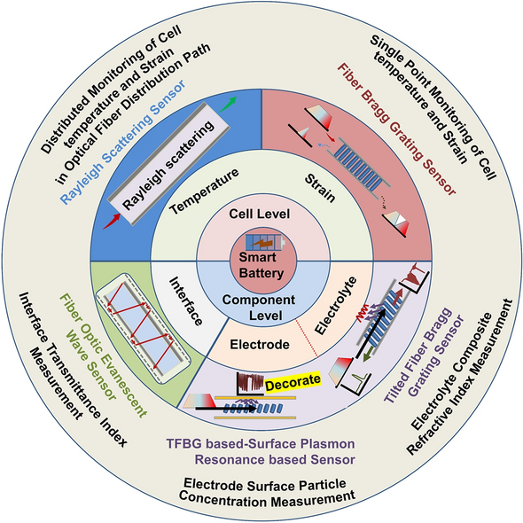
An overview of conductive composite hydrogels for flexible electronic devices
Jiaying Chen, Fangfei Liu, … Xiong Liu

An Environment-Tolerant Ion-Conducting Double-Network Composite Hydrogel for High-Performance Flexible Electronic Devices
Wenchao Zhao, Haifeng Zhou, … Long Zhao

A Review of Rechargeable Zinc–Air Batteries: Recent Progress and Future Perspectives
Ghazanfar Nazir, Adeela Rehman, … Soo-Jin Park
Avoid common mistakes on your manuscript.
1 Introduction
With the development of battery technology, lithium-ion batteries with high specific energy, long life, and high power are being increasingly widely used in electric vehicles or energy storage stations. For batteries, the state of charge (SOC), state of health (SOH) and state of safety (SOS) are strong bases for evaluating the working quality, working reliability and cycle life (QRL) [ 1 ]. With the continuous operation of lithium-ion batteries, frequent safety accidents have cast a shadow on their development.
At this stage, the development of intrinsically safe anodes, cathodes and electrolytes is in the “bottleneck period” [ 2 ], and solving the battery safety problem is urgent. Therefore, improving battery safety through battery self-monitoring and self-management has become an effective method, spawning an extremely important scientific branch— smart batteries . Different from traditional battery intelligence at the module level or system level, the focus for smart batteries is on improving the intelligence of a single battery to enable it to have self-monitoring and self-management capabilities, which is now becoming one of the mainstream research hotspots. The European Union (EU) has made a long-term plan for the development of smart batteries in the technical blueprint of Battery 2030 + Roadmap [ 3 ] released in 2020. Taking electric vehicles as an example, the important “big three parts” are the motors, controllers and batteries, the first two of which have been or can be intelligentized at any time [ 4 , 5 ], while the intelligentization of batteries, especially at the cell level, as the last “plank” of the “big three parts” intelligentization, needs to be focused on. This is mainly because the systems are composed of a large number of single batteries; one aging or defective battery will degrade the system performance or directly threaten the system safety, while a smart battery at the cell level makes consistency less important, and the battery configuration can be flexible [ 6 ].
The development of high-safety, long-life and, high-performance smart lithium-ion batteries (SLIBs) is inseparable from research on the working and aging mechanisms of batteries. Understanding the application principle of observation with advanced sensors embedded in batteries and the impact on the battery performance is also urgent.
During the long service life of a battery, due to the repeated insertion and removal of lithium ions into/from electrodes and the resulting heat generation phenomenon, the battery will experience periodic expansion and contraction, which means that the battery has a kind of “breathing effect”. First, this “breathing” phenomenon generates mechanical stress in the battery, and second, long-term repeated expansion-contraction will produce a “stress fatigue” effect, damaging the active material. In addition to the periodic expansion-contraction, the battery aging, such as thickening of the solid electrolyte interphase (SEI) and decomposition of the electrolyte, will cause abnormal expansion of the battery in the out-of-plane direction [ 7 ], which aggravating the mechanical stress fatigue effect.
In some extremely harsh environments, such as in low temperatures, the Li + intercalation potential (~0.1 V vs. Li/Li + ) of the graphite anode is close to 0 V, and the graphite electrode surface will undergo severe lithium plating [ 8 ]. The lithium plating will sometimes not be in contact with the electrode, and the lithium metal covered by the passivation film will drift into the electrolyte and form “dead lithium” [ 9 ]. In addition, low temperature will accelerate the deposition/decomposition of electrolyte mixture, forming a thick and loose interfacial film [ 10 ]. However, at high temperatures, lithium-ion batteries will have more unexpected side reactions, which will produce side reaction particles [ 11 ]. In addition, the frequent “breathing” effect makes the active material have a non-negligible lattice variation or uneven evolution of the battery structure [ 12 , 13 ], so the weakened lattice and the deteriorated structure lead to defects [ 14 ], such as particle breakage and pulverization of the active material at the micro-level. With the improvement of the battery management system (BMS), the frequent overcharge and over-discharge in the past have been significantly curbed. However, due to the very large number of batteries in a system, micro-overcharge (under normal temperature conditions, one or several overcharges or overcharge to a certain voltage, in which the lithium-ion battery will not fail or thermal runaway) of local batteries is inevitable. The micro-overcharge will lead to excessive release of lithium ions from the positive electrode, leading to collapse of the structure and causing the transition metal to dissolve [ 15 ].
High precision mechanical, thermal, and electrochemical performance and gas [ 16 ] measurements of batteries, such as expansion force, expansion displacement, temperature, high-precision Coulombic efficiency, material degradation, combustible gas, can indicate imperceptible parasitic reactions, side reactions, and even thermal runaway. These measurements help predict the actual working state, safety state, and battery life. However, the imperceptible physical/chemical changes in the internal core of the battery, as well as micro-damage to the battery, are still difficult to accurately understand [ 17 ].
From the above analysis, at the macro-level, the expansion-contraction of battery volume and the temperature changes can be observed through pressure sensors [ 18 ], strain sensors [ 19 ], thermocouples [ 20 , 21 , 22 ], etc. Nevertheless, due to the morphological characteristics and measurement principles of these sensors, they can generally only measure the external state change of the battery and cannot obtain internal information of the battery. With the improvement of the battery energy density [ 23 ], application of new electrode materials [ 24 , 25 ] and demand for upgrading battery technology, there is an urgent need to identify the performance of electrode materials, electrolytes and electrode interfaces inside batteries. Some technologies that can obtain the internal state information of a battery, such as ultrasonic detection [ 26 , 27 ], optical color contrast [ 28 , 29 , 30 , 31 ], and electrochemical window infrared detection technology [ 32 , 33 ]. These technologies have been applied to a certain extent at the laboratory level. However, these methods have large detector components, which are not suitable for embedded installation and mainly focus on point measurement, or require opening of a transparent window into the battery and use of professional color recording and analysis software. They have a certain application value for a single battery, but there is the defect of great difficulty in application at the module level. With the progress of technology, optical fiber sensors are being increasingly widely used in batteries, and their radial dimensions are usually 100 μm or less (excluding coating layer) [ 34 ], which will not cause substantial damage to the battery structure. An optical fiber made of silicon dioxide is stable in nature and can work in a harsh electrolyte environment for a long time without affecting the battery performance [ 35 , 36 ]. Due to the measurement characteristics of optical fibers, in theory, a single optical fiber can measure the status of multiple batteries at the same time, of course, multiple measurement points on one optical fiber can achieve multipoint measurement within one battery. The optical fiber sensing system formed by the layout of multiple fiber optic arrays can achieve large-scale deployment of online battery monitoring. This technical effect has been achieved in reality [ 37 ]. Relying on various measurement principles of optical fiber sensors, such as vertical gratings [ 38 , 39 ], tilted gratings [ 40 ], evanescent waves [ 41 , 42 , 43 ], surface plasmon resonance [ 44 , 45 ], Rayleigh scattering [ 39 , 46 ] and other effects, real-time in-situ measurement of battery internal core key features, such as the stress-strain [ 47 ], temperature [ 48 , 49 , 50 , 51 ], electrolyte refractive index [ 49 , 52 , 53 ], SEI growth [ 36 , 54 ], electrode material redox process [ 41 ] and ion concentration [ 42 ], can now be achieved. This is crucial for understanding the electrode interface dynamics, electrolyte degradation, battery capacity attenuation, and evolution of the electrode material phase and structure. SLIBs prepared by using advanced embedded optical fiber sensors are conducive to clarifying the battery internal processes, thus helping in achieving progress in battery technology.
Against the backdrop of current SLIB research and development, this paper summarizes and evaluates the embedded sensor technology required in the first stage (first stage: develop multisource sensing technology, and achieve transparent to the battery chemical environment. Three stages can be seen in Ref. [ 3 ]) and mainly reviews and comments on the theory and application of advanced optical fiber sensors in understanding the internal mechanisms of a battery, as shown in Fig. 1 . This paper reviews the in-situ online observation of the core reaction mechanisms in a battery using optical fiber sensors and proves that the battery interior can be elucidated by employing advanced optical fiber sensors. To the best of our knowledge, most of the current review studies on the application of optical fiber sensors in batteries concentrate on the sensor working mechanism, simple monitoring processes, and monitoring results. It is unclear how optical fiber sensors can monitor which key processes and achieve what results. Regarding this, this paper reviews and studies the insight ability and future development of quasi-distributed optical fiber sensors, such as the fiber Bragg grating (FBG) sensor, tilted fiber Bragg grating (TFBG) sensor, fiber optic evanescent wave (FOEW) sensor, surface plasmon resonance-based (SPR) optical fiber sensor (the above point-measurement optical fiber sensors are set as quasi-distributed sensor; this is because, as mentioned earlier, multiple measurement points can be fabricated on one single fiber to achieve quasi-distributed measurement) and distributed optical fiber sensor based on the Rayleigh scattering effect in monitoring the core physical/chemical state of lithium-ion batteries and other promising energy storage devices.

Promising optical fiber sensors in battery applications
2 Promising Optical Fiber Sensors in Future SLIBs
At present, the development of lithium-ion batteries is still in the “original” stage. These batteries only have basic charging and discharging functions. The use of advanced optical fiber sensors can help a battery “sense” itself. This section summarizes quasi-distributed optical fiber sensors with broad application prospects in batteries in the future, such as FBG sensors, TFBG sensors, FOEW sensors, SPR-based optical fiber sensors and distributed optical fiber sensors-for example, optical fiber sensors based on the Rayleigh scattering principle. It should be noted that current point measurement-based optical fiber sensors have the capability of multiplexing, meaning that multiple measurement points can be connected in series through one single fiber. In practical applications, using a single point measurement fiber is, in fact, giving up the advantages of optical fiber sensors. Therefore, in this section, the point-measurement optical fiber sensors are classified as the quasi-distributed sensor. This part focuses on describing the effects that different optical fiber sensors can achieve in batteries. The specific working mechanisms and mathematical models of optical fiber sensors can be obtained in the vast majority of relevant literatures. This part will not provide too much description for these.
2.1 FBG Sensor: Battery Routine Mechanical-Thermal Monitoring
FBG sensors, due to their high monitoring precision and fast detection speed, are well-suited for observing changes in the mechanical and thermal behavior of batteries during charging and discharging processes. The variations in these physical characteristics are closely related to the ion transport, lithium ion insertion/extraction, and electrochemical reactions inside the battery, making FBG sensors an excellent tool for monitoring the evolution of battery states. As the optical fiber sensor with the most concise application structure, most mature technology, and lowest cost, the FBG sensor, as shown in Fig. 2 a, has a large number of applications and research achievements at the laboratory level [ 55 , 56 ]. In the industry, before large-scale industrialization, relevant products were also tested [ 35 , 57 ]. This process has gone through the transition from single point FBG to multipoint FBG, from external measurement to embedded measurement, and from a single battery to module and even system-level progress, as shown in Fig. 2 b–f. Generally, an FBG sensor is mostly used to measure the temperature and electrode (cell) expansion inside or outside the battery by using its property of being sensitive to temperature and strain at the same time.

Reproduced with permission from Ref. [ 56 ]. Copyright 2018 MDPI. d Embedded FBG sensor core temperature measurement. Reproduced with permission from Ref. [ 35 ]. Copyright 2018 Elsevier. e Embedding of an FBG in a large pouch battery. Reproduced with permission from Ref. [ 55 ]. Copyright 2017 Elsevier. f Traction battery pack with an FBG embedded in the core. Reproduced with permission from Ref. [ 35 ]. Copyright 2017 Elsevier. g The process of embedding optical fibers in batteries involves the steps of implantation position determination, stacking fixation, encapsulation sealing, and testing in sequence. Reproduced with permission from Ref. [ 35 ]. Copyright 2017 Elsevier
Application of FBG sensors to measure the cell strain-temperature at the laboratory level and before industrialization. a FBG sensor structure and action mechanism. When the battery is loaded with temperature or strain, the FBG grid spacing changes, and the central wavelength of reflected light shifts. The central wavelength shift is linearly related to the temperature and strain. b The evolution of FBG in battery applications. From single point to multipoint, from external to internal, and from single battery to module even system. c Bidirectional strain measurement of an FBG sensor in a single cell.
When the battery experiences electrode expansion and temperature rise due to lithium ion insertion/removal and the redox reaction [ 58 ], the grid spacing of the FBG attached to the electrode surface will change with the battery expansion or temperature rise, and the peak of the reflected light will accordingly shift. As shown in Fig. 2 a, the optical physical quantities of the FBG and temperature-strain can be correlated by reading the position of the reflected light peak [ 59 , 60 ]. Of particular interest is that in an FBG, the temperature and strain show a highly linear relationship with the change in the peak position, which provides great convenience in using the FBG to easily measure the battery temperature and strain and realize decoupling of the two features. Currently, with the maturity of the fiber manufacturing process and grating etching process, the cost competitiveness of FBGs [ 61 ] meets the needs of large-scale industrial applications. Compared to mature and cost-effective optical fibers, the cost of another crucial component of optical fiber sensors—the modulator–demodulator (modem), is currently a significant barrier preventing the widespread application of FBG. The cost of advanced modems typically ranges around CNY 100,000. Placed within the context of electric vehicles, this cost is comparable to the entire battery system cost. Such an expensive modem would significantly increase the overall cost of the relevant energy systems, hindering their widespread adoption. However, with technological advancements, the current size of the simplest laser source emission systems can be reduced to the dimensions of several stacked coins. In the future, if FBG sensor systems are integrated into relevant energy storage systems, the functions of the modem can be progressively decentralized. The laser source system can selectively use a light source with a specific fixed window spectrum, and the receiving and processing modules of the modem can be integrated into the battery management system (BMS). The traditional modem’s auxiliary and heat dissipation modules can be shared with the BMS. In this configuration, the costs associated with relevant hardware and software can be leveled out through mass production. FBG sensors integrated into energy storage systems in the future will be as simple and cost-competitive as traditional sensors. Therefore, the FBG, as a representative of small-size, high-stability and multipurpose optical fibers, may be the most promising optical fiber sensor in the future [ 52 , 62 ].
Among the many advantages of FBG, an important issue that cannot be ignored is the force-temperature coupling behavior. That is to say, when FBG is subjected to battery temperature and external force, both of them will simultaneously cause displacement of the FBG center wavelength. How to decouple force-thermal parameters is a key issue. Currently, the conventional solution is the dual-FBG-decoupling method, where two FBGs with different force-thermal parameters are used to simultaneously measure the battery, or one FBG is fixed, while the other FBG is released to make it only sensitive to temperature, and then the relevant parameters can be decoupled by solving a simple one-dimensional quadratic equation system; Secondly, based on simple mathematical principles, knowing one unknown quantity can solve another unknown quantity. Usually, a thermocouple or strain gauge can be attached next to the FBG to solve another unknown quantity with known temperature or strain; In addition, decoupling can also be achieved for additional geometric structures of FBG, such as arranging the FBG up and down, causing the mechanical vector of FBG to change in the opposite direction, or using the thermal expansion and contraction effects of the structure to artificially eliminate changes caused by temperature effects. All of the above methods can achieve decoupling measurement of FBG force-temperature parameters, promoting the application of FBG in in-situ monitoring of batteries.
A key aspect for the stable operation of optical fibers in batteries is the correct embedding of the fibers inside the battery, as illustrated in Fig. 2 g. Taking the embedded application of FBG optical fibers in pouch batteries as an example. One initial consideration is the embedding process. Typically, the optical fibers are embedded between the electrode sheets before battery assembly, with the position generally at the geometric center of the electrode. Subsequently, the optical fibers are stacked and clamped between the electrode sheets to achieve initial fixation. Then, the battery jellyroll is placed within the aluminum-plastic film for positioning. The second critical aspect is sealing. A research team used materials consistent with the heat-sealing glue for sealing electrode tabs to envelop the optical fibers. This ensures fixation at both ends of the aluminum-plastic film, achieving the internal fixation of the optical fibers within the battery. Subsequent comparative testing is conducted on batteries with and without embedded optical fibers, using the HF content as an indicator. By recording the penetration of moisture and the HF generated by the reaction with the electrolyte, the sealing performance of the two encapsulation methods is compared. The results show that after 4 weeks, the embedding of optical fibers did not compromise the sealing integrity of the battery [ 35 ] .
Another crucial consideration in the application of FBG sensors in batteries is whether the sensor can maintain long-term stability and proper functionality within the battery. This is fundamental for the sensor to effectively monitor the battery’s status without interfering with its normal operation. Regarding the former, Raghavan et al. [ 35 ] discovered that FBGs made of silicon dioxide material, when coated with a special coating, can fully withstand the electrochemical effects of daily battery use. On the one hand, properly coated FBGs can withstand high temperatures ranging from 200 to 800 °C (a temperature range far exceeding the normal operating temperature of batteries and even surpassing certain characteristic temperatures during battery thermal runaway). On the other hand, the optical fibers can endure the stretching effects caused by changes in battery volume, allowing them to operate within the elastic region to ensure a highly linear response. Also, Raghavan et al. [ 35 ] comparing batteries with embedded FBGs to control batteries, found that both exhibited a capacity decline rate of less than 20% after more than 1100 and 1300 cycles, respectively. The Coulombic efficiency for both scenarios exceeded 0.999, demonstrating that the batteries with embedded FBGs did not significantly impact battery performance. Similar validation was performed by Huang et al. [ 36 ], who found no significant differences in cycling capacity and rate performance between batteries with embedded FBGs and control batteries over at least 100 cycles.
2.2 TFBG Sensors: Electrolyte Internal Environmental Monitoring
For a traditional FBG, the grating is perpendicular to the fiber axis. When a special manufacturing process is used to tilt the grating direction and axis to a certain angle, a tilted FBG sensor is obtained, as shown in Fig. 3 a. In this case, the reflected light will not strictly reflect back to the incident end; instead, the reflected light is transmitted to the cladding and then coupled with the external environment. When a TFBG is embedded into the battery, it interacts with the electrolyte environment through the reflected light from the overflowing optical fiber, acting like a “nerve”, constantly monitoring the internal environment of the battery’s “body fluid” (electrolyte). The reflected light spectrum will exhibit a different mode from that of the FBG. There are many coupling modes in a TFBG, and light from the core can be coupled as follows: first, a subset of the large number of modes can be guided by the (much larger) cladding of the fiber; second, leaky modes of the cladding arise; and then, highly directional light beams even radiate out of the fiber [ 40 ].

Reproduced with permission from Ref. [ 49 ]. Copyright 2021 Royal Society of Chemistry. b The evolution of electrolyte refractive index with battery health state in TFBG Wavelength. The suspended dead lithium, gas production, and degradation of the electrolyte’s performance caused by battery aging can all lead to significant changes in the comprehensive refractive index of the electrolyte detected by TFBG, which is reflected in the mode conversion of various modes in TFBG, including the center position of the mode peak and the power of the peak. Reproduced with permission from Ref. [ 49 ]. Copyright 2021 Royal Society of Chemistry
TFBG monitoring of the electrolyte environment. a Working mechanism and application scenario of the TFBG in batteries. When the incident light enters the fiber and reaches the grating, the light meeting the Bragg condition will undergo Bragg reflection, while the light meeting the conditions of a certain order cladding radiation mode will be coupled into the cladding and exchange energy with the external environment, realizing monitoring of the surrounding electrolyte environment.
The light meeting the conditions of a certain order cladding radiation mode will be coupled into the cladding and exchange energy with the external environment, so the external environmental state can be found from the spectrum. After long cycling, a battery will experience excessive consumption or side reaction of the electrolyte, leading to the appearance of micro-solid particles in the electrolyte [ 49 ]. The lithium will be coated by an insulating passivation film and separate from the electrode, becoming “dead lithium” suspended in the electrolyte [ 63 ]. The consumption of the electrolyte itself and these substances floating in the electrolyte will alter the chemical composition of the battery itself, consequently causing changes in the optical signal sensed by TFBG. Thus, the TFBG sensor can easily “perceive” the turbidity process of the electrolyte by measuring the change in the refractive index caused by these phenomena (Fig. 3 b). Because the Bragg mode and cladding mode are sensitive to the temperature and refractive index [ 64 , 65 ], respectively, and there is no cross-sensitivity between them, the TFBG sensor has significant advantages in eliminating interference between temperature sensing and “seeing” substantial changes in the electrolyte.
Through the analysis of a case, it can be found that the TFBG has a unique advantage in sensing changes in the battery electrolyte environment. The reason why TFBG can achieve this unique monitoring effect is mainly based on its core-cladding mode coupling. TFBG uses a special process to tilt the grating, thereby introducing dozens or even hundreds of narrow linewidth cladding mode excitations, while retaining the backward conductive core mode that meets the Bragg condition. This allows these cladding modes to have rich mode field distributions and different response characteristics to the environment. The consumption of electrolyte inside the battery or energy storage device, the detachment of active materials, and the dissociation of “dead Li” may trigger different coupling modes. In the future, with the progress of pattern recognition technology, different aging and failure paths of the battery may be understood through TFBG. In addition, TFBG can achieve other unexpected effects through special additional processes by using techniques such as fiber taper and staggered fusion. TFBG can monitor the vibration, bending, and other environments of energy storage devices, combined with materials such as liquid crystals and magnetic fluids. TFBG can even monitor electric and magnetic fields, which may be an effective way to monitor micro-internal short circuits (electronic current induced magnetic field fluctuations in batteries) in the future. The extremely narrow spectral bandwidth of TFBG provides ultra-high detection sensitivity and resolution for its sensing. Combined with SPR technology, TFBG can achieve precise monitoring of important electrochemical processes in batteries, which will be detailed in the following part. In terms of cross-sensitivity decoupling, by referring to the wavelength and power level of the TFBG backward reflection fiber core mode, the inherent temperature cross-sensitivity problem in the sensing measurement process is completely eliminated, which greatly improves the accuracy and stability of the sensor. The embedded operando monitoring application of TFBG in batteries or energy storage devices will have great development space.
TFBG sensors and FBG sensors do not have essential differences in material and composition. The most notable structural difference between the two lies in the tilt angle of the internal grating. While the grating of FBG sensors is perpendicular to the axial direction, TFBG sensors have a certain tilt angle with respect to the axial direction. This tilt angle depends on the manufacturing process and the mode of interest to the researcher. The embedding form and corrosive environment faced by TFBG in batteries are similar to those of FBG. Referring to the working conditions and environments of FBG, it can be inferred that TFBG generally ensures long-term stability in batteries. Additionally, similar to the grating of FBG, TFBG’s grating has protection in the form of a fiber core and coating layer on the outer side. The influence of the battery environment on the grating can be neglected, and therefore, the grating’s ability to reflect incident light will not be significantly affected. In this regard, Liu et al. [ 66 ] conducted cycles of over 400 hours on TFBG in Li-S batteries. The experimental results showed that TFBG maintained good wavelength stability with high repeatability and minimal impact on the battery’s performance. This preliminary evidence suggests the potential for stable operation of TFBG in batteries. However, the long-term performance degradation and changes of TFBG after prolonged operation throughout the lifecycle of the battery remain one of the key research issues. This is crucial for determining whether the sensor can effectively perceive changes in the battery’s internal environment over time.
2.3 FOEW & TFBG-SPR Sensors: Electrode Interface Monitoring
The TFBG mentioned in the previous section can perceive the electrolyte environment around optical fibers like a nerve, while the FOEW and TFBG-SPR sensors introduced in this part can observe the state of electrode interfaces in detail like dermatologists. While in theory, total reflection will occur when light is emitted from an optically dense medium to an optically thinner medium, both practical observations and theoretical developments increasingly demonstrate that leaked energy can be detected in a thin layer (approximately 100 nm) at the optically dense–thinner interface [ 67 ]. This phenomenon is referred to as an evanescent wave. By using this principle and combining it with an optical fiber sensor, a detailed “diagnosis” of the electrode surface can be achieved, as shown in Fig. 4 a.

Reproduced with permission from Ref. [ 70 ]. Copyright 2017 ACS Publications. Ref. [ 71 ]. Copyright 2022 ACS Publications. b The loss of reversible lithium leads to changes in the detectable optical properties of FOEW. The optical transmissivity of the evanescent wave is related to the lithium-ion concentration on the surface of the graphite particles, when the capacity of the lithium-ion battery declines after long cycling due to the reduction of recyclable graphite lithium content, the FOEW transmission amplitude decreases. Reproduced with permission from Ref. [ 42 ]. Copyright 2020 Elsevier. c SPR sensor: Total internal reflection of incident light occurs at the interface between an optical fiber and a metal film, and the evanescent wave causes regular oscillation of metal surface electrons at the interface between the metal film and medium, which excites a surface plasmon wave. When the incidence angle or wavelength is a certain value, the wave vectors of the surface plasmon wave and evanescent wave are equal along the interface between the metal film and medium such that the wave vectors match, and the two resonate. The incident light is coupled with the surface plasmon wave through the evanescent wave, and the energy is strongly absorbed by the metal surface electrons, which makes the reflected light energy sharply drop and generates the surface plasmon resonance phenomenon. Reproduced with permission from Ref. [ 44 ]. Copyright 2022 MDPI. d The changes in ion concentration and state on the electrode surface affect the SPR waveform. The SPR mode is closely related to the electrode surface polarity, and as the potential gradually becomes positive, the SPR wave becomes deeper. At the same time, the core mode is not related to the polarity, and research shows that it is only related to temperature and only changes with temperature. Reproduced with permission from Ref. [ 45 ]. Copyright 2018 Springer Nature
FOEW sensor and SPR sensor for battery surface monitoring. a FOEW sensor: The evanescent wave effect occurs when a light wave is incident from a dense medium to a light sparse medium, and total reflection occurs. The evanescent wave is a surface wave. Its amplitude exponentially decreases with increasing depth perpendicular to the interface, and the phase changes with the tangential direction.
In a battery, pristine graphite has a relatively low free carrier concentration (∼10 −4 free carriers/atom) at room temperature. As lithium ions intercalate and transfer/delocalize their 2 s electron into the graphite π-band, the carrier density of the graphite layer adjacent to the lithium layer increases. This increase in the free carrier concentration causes alterations in the graphite’s electrical, chemical, thermal, magnetic and optical properties [ 68 ]. Through the interaction of the aforementioned FOEW sensor with graphite particles in a lithium-ion battery in multiple cycling, studies have found evidence indicating that the optical transmissivity of the evanescent wave is related to the lithium-ion concentration on the surface of the graphite particles [ 42 , 69 ]. The optical intensity is associated with the degree of lithiation on the electrode surface, and the lithium ion concentration becomes the main factor affecting the transmissivity. As the battery cycling continues, aging inevitably occurs. In this case, the loss of recyclable lithium results in a reduction of the lithium content in the active material, and this degradation effect is reflected in the light spectral characteristics (Fig. 4 b). In the previous section, a TFBG can “see” the electrolyte turbidity process; however, changes in electrolyte turbidity or salt concentration will not affect the observation of transmission by an FOEW sensor, meaning that the salt concentration in the electrolyte will not affect the evanescent wave signal [ 41 ]. Thus, by eliminating the related influencing factors through this phenomenon, the measured quantity is only related to the lithium ion concentration. Considering the short penetration depth of evanescent waves, the response of an FOEW sensor is likely to be affected by the surface conditions of electrode particles near the sensing area [ 41 ].
In the previous analysis, we can see that the FOEW signal shows sensitivity to the lithium concentration on the surface of graphite particles. By monitoring the evolution of the optical transmissivity, the relationship between the transmission amplitude and available capacity can be obtained, which facilitates monitoring the battery’s State of Health (SOH) [ 42 ]. When the capacity of the lithium-ion battery declines after long cycling due to the decrease in the lithium content of recyclable graphite, the FOEW transmission amplitude decreases. The transmission amplitude of an FOEW sensor has been successfully correlated with the SOH of the battery [ 70 ].
Like an FOEW sensor in sensing characteristics (electrode surface monitoring), an SPR sensor uses the strong electromagnetic energy localization effect in the layer adjacent to a metal surface by applying a thin metal coating to the optical fiber surface. Through the stimulation and detection of optical signals, surface plasmon waves can offer heightened sensitivity of chemical changes in the battery [ 45 , 72 ], as shown in Fig. 4 c, d.
Using the TFBG mentioned in the above section, the surface of the TFBG is coated with a metal layer so that the SPR sensor has both the TFBG multimode characteristics and SPR sensitivity. In a TFBG, the core mode is completely insensitive to electrochemical changes. Therefore, the spectrum of the core mode can be referenced in terms of the power and wavelength to eliminate the impact of any system instability (it acts as an in-situ thermometer, monitoring changes in wavelength, for example, intensity change or the wavelength of the core mode) [ 45 ]. When a gold-plated TFBG sensor is closely attached to an electrode surface, the change in the charge density and ion distribution around the electrode can be directly monitored through the change in the SPR signal [ 45 ], for example the SPR power evolution. So, it’s evident that the differential curve of the SPR power corresponds to the real-time change rate of the ion concentration. The two characteristic peaks in the discharge stage correspond to the maximum change rate of ions. And the mapping of the differential SPR power with the voltage corresponds to the change rate of the ion concentration under different potentials [ 73 ].
The previous section introduced that the use of TFBG cladding mode resonance peak can achieve detection of changes in the electrolyte environment state by monitoring changes in the refractive index of the electrolyte around the fiber. However, the use of TFBG higher-order cladding mode and mutual excitation of SPR with the metal film material on the grating surface can achieve higher sensitivity in monitoring changes in the internal environment of the battery. Compared to bare TFBG, the internal environment monitoring of the battery under the TFBG-SPR mechanism can achieve higher sensitivity in monitoring, and it has smaller temperature cross-sensitivity, which can greatly reduce the impact of temperature factors on measurement and simplify the measurement device.
The decomposition of SEI [ 74 ], the occurrence of graphite delamination effect [ 74 ], and the generation of combustible gases [ 75 ] can all impact the stability of the battery’s internal environment. The entry of related substances into the electrolyte, the reaction with the electrolyte, and even the consumption/depletion of the electrolyte can affect both the liquid refractive index and the interface refractive index of the battery’s internal environment. Evidence of battery degradation process can be found through historical comparison in optical fiber spectroscopy.
Based on mechanism analysis, both the FOEW sensor and SPR sensor need to be closely attached to the electrode surface due to the short penetration distance of energy. In this case, due to the blocking of lithium ion diffusion during the battery lithiation process, lithium will be enriched around the optical fiber [ 44 , 70 ], leading to local electrode variation and even lithium plating. Now, it is doubtful whether the monitored electrode characteristics can represent the overall situation. A more serious issue is that if the enriched lithium pierces the separator [ 45 ], it will trigger thermal runaway, endangering the battery safety. Embedded sensors pose a ‘double-edged sword’ effect-monitoring safety and threatening it. Researchers must address this challenge.
For FOEW sensors, stable observations are typically achieved using silicon dioxide material. In a study exploring the aging performance of optical fibers in more severe environments, traditional silicon dioxide was replaced with high-polymer plastic optical fibers. Accelerated aging tests were conducted, and the experiments showed that, under acidic corrosive conditions, the optical fibers exhibited no abnormalities after cycling for 1000 h at 50 °C and 2000 h at 60 °C [ 76 ]. The fiber’s attenuation remained consistent. Considering this, we conducted a reasonable extrapolation, anticipating that FOEWS with silicon dioxide material could maintain stable operation in corrosive environments. TFBG-SPR sensors, like traditional telecommunications-grade optical fibers, also use mature silicon dioxide material and a gold metal coating. A study clearly indicates that, through proper encapsulation, as long as the geometric deformation of the optical fiber does not exceed its limit state, TFBG-SPR sensors can maintain sufficient stability and correct output in battery environments to achieve accurate parameter observations [ 45 ].
2.4 Rayleigh Scattering Optical Fiber Sensors: Global Thermal–Mechanical Monitoring
The sensors introduced in this section based on the Rayleigh scattering principle are like physical examination doctors, capable of monitoring the overall mechanical and thermal health status of the battery. The sensors introduced above, whether structural FBG, TFBG sensors or functional SPR and FOEW sensors based on optical principles, have an inherent disadvantage; that is, they can only measure the battery status at one single point at the functional location. If more functional nodes are added, then these sensors can theoretically measure data at multiple points in the battery to form a quasi-distributed measurement structure but still cannot globally monitor the status of the battery (along the optical fiber path). Correspondingly, distributed optical fiber sensors using Rayleigh scattering, Raman scattering or Brillouin scattering can measure the full path range along the optical fiber distribution. Raman scattering is primarily sensitive to temperature, making it challenging for multiparameter measurements in batteries with structural changes [ 77 , 78 , 79 ]. The self-emitted Brillouin scattering has a weak light intensity, with restricted resolution and response time for related sensors [ 51 , 80 ]. Due to the inherent multisource parameter sensing capability and high spatial resolution [ 46 ], distributed sensors based on Rayleigh scattering have been increasingly studied and have become mature and practical, as shown in Fig. 5 .

Reproduced with permission from Ref. [ 39 ]. Copyright 2021 IOP Publishing. Reproduced with permission from Ref. [ 51 ]. Copyright 2019 AIP Publishing. b Comparison between distributed temperature measurement based on Rayleigh scattering effect and FBG quasi-distributed temperature measurement. The spectrum of temperature measurement based on Rayleigh scattering effect in time and space is more intuitive than that of FBG measurement, and the identification of temperature hot spots is more accurate. Reproduced with permission from Ref. [ 39 ]. Copyright 2021 IOP Publishing
Distributed optical fiber sensing system based on the Rayleigh scattering principle. a Measurement mechanisms for different distributed optical fibers. When the particle size is much smaller than the wavelength of the incident light (less than one tenth of the wavelength), the scattered light intensities in each direction are different, and the intensity is inversely proportional to the fourth power of the wavelength of the incident light. This phenomenon is called Rayleigh scattering.
The distributed sensor based on the Rayleigh scattering principle can be used to conduct real-time online measurements of the global state of the battery with very high spatial resolution. An experiment on the 18650-type lithium-ion battery showed that this kind of distributed measurement method can enable temperature and strain imaging of the battery with millimeter-level spatial resolution [ 39 , 81 , 82 ]. The high-precision measurement of global physical parameter, including distributed temperature, coupled with corresponding technical algorithms, can provide a more detailed analysis of the battery's operational status [ 83 ]. The use of distributed sensors based on the Rayleigh scattering principle to achieve high-precision estimation of battery core state parameters is more convenient when reducing equipment demand after calibrating relevant internal and external battery state equations in advance [ 84 ]. Distributed sensing can provide increasing amounts of abundant battery state information so that a more complete grasp of the battery can be obtained. Theoretically, in general battery applications, distributed sensors can be segmented and only collect parameters at fixed positions, making them similar to FBGs, which can reduce the amount of data. When abnormal conditions are detected, the fault location can be identified in this application through dynamic adjustment of the monitoring points (in this case, the sensor is similar to an FBG with an adjustable grid spacing).
One of the advantages of optical fiber sensors based on Rayleigh scattering, compared to several sensors mentioned earlier, is their capability for distributed measurements, a characteristic emphasized repeatedly in the paper. An essential requirement for achieving high-resolution monitoring of battery states along the entire distribution path of optical fibers is the uniformity and stability of the fibers at various positions. Any variation in the properties of the fiber at a specific location can lead to errors in the corresponding sensing. In this regard, Yu et al. [ 85 ] implanted Rayleigh scattering optical fibers into the interior of 18,650 batteries. After over 60 cycles, they found that the impact of the optical fibers on the batteries was nearly negligible. Furthermore, through continuous monitoring for 20 h, two different Rayleigh scattering optical fibers demonstrated highly reproducible temperature monitoring in the batteries. These findings demonstrate that distributed fibers within the battery can ensure continuous and stable operation for extended periods, ensuring the long-term performance stability of embedded sensors.
The characteristics and possible application scenarios of different optical fiber sensors are shown in Table 1 , which can guide the selection of relevant optical fiber sensors in practical use.
Now, with the feasible implementation of the technology, advanced optical fiber sensors can monitor and diagnose battery strain, temperature, electrolyte and electrode degradation. The distributed sensors can be used in daily applications to achieve comprehensive physical examination of the battery “physical state” and “nidus” identification. With its small size, high stability and environmental adaptability, the advanced optical fiber sensor will be of excellent help in realizing battery intelligence in the future.
3 Embedded Optical Fiber Sensors Help Strengthen Battery Safety
Sensing the changes in the basic properties (stress, strain, and temperature) of a battery is not the key problem for the application of embedded sensors in the battery; instead, the “mission” of embedded optical fiber sensors is to determine the phase change process, electrochemical behavior, interface dynamic response characteristics and safety evolution characteristics of the key materials inside the battery. Thus, optical fiber sensors can provide insight into the battery core reaction state to help enhance safety. In this section, in-situ real-time online monitoring of the battery phase change behavior, electrode and interface dynamics and evolution of battery safety characteristics using advanced embedded optical fiber sensors is reviewed.
3.1 Early Warning of Battery Health State Enabled by Mechanical-Thermal Signals of Optical Fiber Sensors
According to the working principle of the battery, during the charging and discharging process, lithium ions are periodically inserted into and removed from the positive and negative electrodes through the electrolyte. In this process, there will be redox reactions near the cathode and anode interface [ 86 , 87 ]. During this process, an SEI will be generated on the anode surface. At the same time, the material lattice is “filled” by and “stripped” of lithium, leading to expansion and contraction of the battery [ 7 , 88 , 89 ]. With the redox reaction, the battery releases heat, and the temperature synchronously rises. As the battery cycling continues, thickening of the SEI and the formation of gas due to the liquid electrolyte reaction will lead to an increase in the battery volume [ 90 ], and the abnormal side reactions will lead to an abnormal temperature rise in the battery [ 91 ]. Furthermore, the transformations in optical fiber signals caused by electrolyte aging, floating of dead lithium, and various physicochemical changes in batteries have been thoroughly discussed in the preceding parts.
From the above observations, we can see that, firstly, during the battery’s service life, monitoring changes in the battery’s volume can detect a decline in the health status before electrical and thermal signals. Specifically, as lithium ions cycle and the breakage-reformation of the solid electrolyte interface (SEI) occur, active lithium is continuously consumed. If judged solely from a capacity perspective, there is a long period of linear capacity decline before a “dive” in the capacity of lithium-ion batteries. However, from a mechanical perspective, noticeable accelerated aging behavior of battery expansion can be observed several days or even weeks before the capacity dive, providing an early indication of the decline in the battery’s health status. Furthermore, by utilizing optical fiber measurements of changes in battery expansion behavior and employing simple binary thresholds, we can detect the occurrence of phenomena such as lithium plating very early on. This helps prevent accidents and disasters caused by lithium plating, providing an early warning for the battery’s deteriorating health status. In addition, based on the mechanical characteristics of optical fibers, through simple technical operations, it is currently possible to observe the battery expansion caused by the thickening of SEI, lithium plating, and gas generation. The expansion rates and characteristics of these three phenomena have distinct differences. Through further research, if decoupled observations of the three main expansion behaviors can be achieved, the mechanical monitoring of battery health will be further refined, potentially allowing for a more detailed differentiation of the evolution of battery health. Then, temperature is highly sensitive for batteries, and optical fiber sensors embedded in each cell can provide detailed temperature monitoring. This offers a more accurate and comprehensive data foundation for the thermal management system, helping to ensure uniform temperatures within the battery pack and contributing to extending the battery’s lifespan. Regarding the health of the electrolyte, there is a significant difference in the spectral signals between healthy electrolyte and electrolyte with suspended impurities. With further research, if we can extract the spectral signal characteristics corresponding to different impurities and concentrations, we can conveniently detect early signs of events that may harm battery health and safety.
Visible, the sensitivity of advanced optical fiber sensors to temperature-strain and the refractive index of the liquid environment enables simultaneous observation of the macro- and micro-properties of the battery and prediction of the aging state of the battery [ 85 , 92 ]. Therefore, based on macroscopic changes in the battery’s physicochemical characteristics, such as temperature and stress (strain), as well as microscopic changes, such as alterations in refractive index, the battery can perceive the early evolution of its own health state.
Because lithium will be deposited on the surface of the metal sensor, incomplete insulation treatment and sensor metal burrs may cause short circuits in the battery. Some studies have implanted thin-film metal sensors into batteries. Although these sensors with extremely small out-of-plane dimensions seem well-suited for monitoring the internal electrothermal characteristics of batteries, it is easily understood that these sensors generally have larger in-plane dimensions. This planar sensor design often hinders ion transport at its location, leading to increased polarization and impacting battery performance. With the increasing demand for fine management of batteries, the conventional approach of monitoring module voltage and surface temperature is no longer suitable for existing battery systems. As research advances, more conclusions indicate that when voltage sensors or thermocouples detect abnormal voltage signals or temperature rise in the module, the internal temperature of the battery may have already surpassed irreversible thermal runaway characteristic temperatures. At this point, such delayed monitoring may not be conducive to early warnings for battery safety. It is also essential to emphasize that with a substantial increase in the number of batteries in energy storage systems, achieving fine control with traditional electro-thermal sensors may require installing sensors for each individual battery. Faced with systems composed of thousands of batteries, this approach leads to an exponential increase in the complexity of signal reception and processing, demanding extensive software and hardware requirements. Traditional battery sensors are increasingly unable to meet the demands of fine battery management and technological development.
The material properties and geometric characteristics of optical fiber sensors enable them to adapt to the complex and harsh environments within batteries. Embedded optical fiber sensors can promptly detect anomalies in the battery that are imperceptible externally. Additionally, the multiplexing capability of optical fiber sensors makes them highly suitable for scenarios with a large number of batteries. Taking the example of a standard Fiber Bragg Grating (FBG) sensor, current technology allows the inscription of 30 gratings on one single FBG. Consequently, one optical fiber cable can provide real-time monitoring for 30 batteries, significantly reducing the hardware interface requirements to one-thirtieth of the original. With further understanding of the time domain and frequency domain characteristics of optical fiber, some companies (e.g., Changfei in Wuhan) can inscribe tens of thousands of gratings on a single fiber. In theory, for an energy storage station comprising tens of thousands of batteries, a single fiber optic sensor could achieve the effects that would traditionally require tens of thousands of regular sensors. This is highly advantageous for fine battery management.
Thanks to its intrinsic safety, a silica-based optical fiber sensor has a unique advantage in gaining insight into the internal state of the battery. By implanting the functional optical fiber into the electrode interface and the electrode active material, different characteristics can be observed. As shown in Fig. 6 , due to the axial and transverse alternating stress effect within the active material, the optical fiber embedded in the material exhibits a peak splitting characteristic that differs from the optical fiber at the material interface [ 86 ]. The occurrence of this phenomenon is closely related to the embedding of lithium and the resulting multidirectional expansion of the active material, insights that are inaccessible to external surface sensors of the battery. In addition, remarkable findings have been discovered through the use of optical fiber sensors. The diffusion of lithium in the electrode is not uniform. The interaction between fast and slow lithium-ion diffusion processes leads to uneven insertion of lithium ions [ 93 , 94 ]. The natural observation advantage facilitates an understanding of the charge and material transmission characteristics, as well as elucidation of the relationship between the changes in the electrode structure and thermal-mechanical stress at the electrode–electrolyte interface [ 95 ]. Beyond conventional battery state estimation, an apparent application value lies in enhancing the safe usage of high-performance batteries [ 96 , 97 ]. The battery mechanical, electrical and thermal characteristics can be adjusted based on the information of optical fiber sensors so that the battery always has the best performance and safety. In general, the contradiction between “fast” and “stable” that is never easy to tune in the field of fast charging (high power discharging) applications can be overcome [ 98 ].

Reproduced with permission from Ref. [ 99 ]. Copyright 2022 Springer Nature
Observation of the “breathing” effect of the battery by an advanced optical fiber sensor. The fiber has different wavelength response behaviors at different interface positions, and the bidirectional stress inside the electrode causes splitting of the fiber wave peak, indicating anisotropy of the electrode active material.
3.2 Electrochemical Reaction State Reflected by Spectral Signals of Optical Fiber Sensors
In the previous section, the importance of monitoring the constitutive properties of the battery, such as the temperature, stress and strain, was discussed. If this basic information about the battery is unclear, then mastery of the key factors that affect the battery life and service performance, such as solid–solid and solid–liquid interface properties and dynamic characteristics, will be lost [ 36 ]. Some research teams have proven that the chemical information contained in the optical sensing signal can help in understanding the characteristics of battery parasitic reactions and interface growth dynamics [ 36 ]. Embedded optical fiber sensors are similar to “non-invasive inspection”; they can clarify the electrochemical reaction process inside the battery.
The results of monitoring the temperature rise and pressure change characteristics inside a battery utilizing an optical fiber sensor with a modified structure are shown in Fig. 7 a. The appearance of the peak-iic temperature rise is accompanied by an increase in the pressure, this indicates the generation of gas. Notably, this phenomenon is absent in the subsequent cycle, suggesting that this effect is linked to the formation of an SEI [ 36 ]. In addition, the unique optical sensing method can be used to adjust the interface chemistry through heat release, chemical reaction at the electrode–electrolyte interface, and reaction activity of electrolyte additives. This approach enables a comprehensive understanding and optimization of the battery material ratio to attain superior performance [ 54 ].

Reproduced with permission from Ref. [ 36 ]. Copyright 2020 Spring Nature. b Understanding the relationship between the redox of Fe in an LFP-based battery and the strength of the optical fiber output, and understanding the material reaction process. Reproduced with permission from Ref. [ 41 ]. Copyright 2021American Chemical Society
New understanding of the electrochemical reaction through advanced optical fiber sensors. a An improved microstructure optical fiber was used to understand the electrochemical reaction state of the battery by observing and calculating the heat release, chemical reaction at the electrode–electrolyte interface and reactivity of electrolyte additives.
The use of advanced optical fiber sensors can bring a new understanding of and thinking about the electrochemical reactions. Taking a lithium iron phosphate (LFP) battery as an example, an intuitive and robust correlation can be established between the optical signal sensed by an optical fiber and the concentration of lithium or even the redox reaction of battery elements [ 42 ]. As shown in Fig. 7 b, when the LFP is oxidized, the signal strength increases. When most of the LFP is oxidized, the strength remains unchanged, and then, the strength decreases when the current drops below zero. At this time, FePO 4 is reduced to LiFePO 4 . After a complete redox cycle, the signal strength recovers to the same level [ 41 ]. More detailed analysis revealed that because the charge is controlled by the potential, the current generated is related to the amount of iron oxidized/reduced [ 43 ]. When the LFP is fully charged or discharged, the current drops to almost zero, which means that the optical response alternates between two levels of values and remains constant. Starting from the charged state, when the potential becomes sufficient to oxidize increasing amounts of Fe 2+ , the current increases, and lithium ions are extracted from the olivine structure. After a period of time, the current becomes limited due to mass transfer. When all Fe 2+ is completely oxidized, the current gradually drops to almost zero. According to this phenomenon, chemically lithiated Li 0.6 FePO 4 shows a higher absorption intensity than delithiated FePO 4 , which leads to a high light intensity in the charged state and a low light intensity in the discharged state [ 43 ].
The above analysis clearly indicates that the changes in relevant spectral signals, combined with electrochemical theory can perfectly explain the electrochemical reaction process inside the battery. From this, it can be seen that when the monitored active material undergoes aging, its reaction intensity will change. By comparing historical changes in spectral data, it is very easy to obtain the cause of the failure. To put it further, it can at least eliminate certain probability events and help researchers carry out research in the correct direction. In normal use, an advanced optical fiber sensor is very important for obtaining a deep understanding of the redox reaction and accompanying battery processes, which can help in adjusting the working conditions of the battery in time, improving the battery’s working conditions, and maximizing the service life of the battery.
In the process of long-term cycling, a problem that cannot be ignored is the occurrence of detrimental side effects, as shown in Fig. 8 a, including physical and chemical effects. Electrode cracking causes damage to the integrity of the battery structure, which may lead to shedding of active materials. Taking metal dissolution as an example, on the one hand, the dissolved metal will change the electrolyte environment; on the other hand, it will hinder the insertion of active lithium, resulting in attenuation of the battery life and capacity [ 100 ]. Moreover, shuttling of redox contaminants in the electrolyte and serious lithium plating [ 52 ] greatly harm the battery performance and safety. An optical fiber sensor can intuitively perceive the changes in the electrolyte “internal environment” (refractive index, transmissivity) [ 89 ] through displacement of the peak signal and changes in the optical signal energy [ 52 ], as shown in Fig. 8 b, c, and then the possible battery attenuation and performance degradation of electrodes, interfaces, and materials can be deduced.

Reproduced with permission from Ref. [ 52 ]. Copyright 2022 Springer Nature. b Effect of different electrolyte concentrations on the light intensity in the SPR mode and core mode. Reproduced with permission from Ref. [ 45 ]. Copyright 2018 Springer Nature. c Overall effect of the salt concentration on the light intensity. Reproduced with permission from Ref. [ 49 ]. Copyright 2021 Royal Society of Chemistry
An advanced optical fiber sensor provides insight into the internal environment of an electrolyte. a Factors that cause deterioration of the internal environment of the battery electrolyte during the entire life.
3.3 Large Margin Early Warning of Battery Thermal Runaway Through Optical Fiber Sensors Signals
A troublesome problem for battery safety is the identification and early warning of thermal runaway. Common battery thermal runaway safety warning methods are limited by the sampling channel, data volume, and sensor technology and can only measure the voltage and surface temperature at several nodes at the module level [ 7 , 101 ], detect the gas in a ventilation channel, or monitor safety using the battery’s impedance characteristics [ 102 ]. These technologies have some shortcomings, limited by the sampling principle and sampling location (usually sampling is conducted outside the battery), when the system detects abnormal signals, the battery may already be in an irreversible failure state, or the battery structural integrity may have already been fatally damaged. This kind of “hindsight” safety supervision and early warning is obviously not suitable for high-margin pre-warning of battery issues [ 103 ].
An optical fiber sensor, as described in the previous part, can perform real-time online monitoring of the internal environment of the battery. With the characteristics of being small, stable and accurate, it can be used to achieve embedded and advanced battery safety early warning, and catastrophic failures and extreme abuse can be instantly identified [ 52 , 104 ]. In this way, the embedded optical fiber sensor endows the battery with “pain sensing nerves”, allowing the battery to perceive danger earlier and more reliably.
When the battery is continuously subjected to abuse conditions, whether mechanical abuse [ 105 , 106 ], electrical abuse [ 107 ] or thermal abuse [ 108 ], it will eventually evolve into a state of thermal runaway. As shown in Fig. 9 a, thermal runaway typically includes the following processes: First, the SEI decomposes, then the anode collapses, and the embedded lithium reacts with the electrolyte. The positive active substance decomposes with the electrolyte lithium salt, the electrolyte solvent is oxidized, and the embedded lithium reacts with the adhesive. The separator is melted or broken, and the positive and negative electrodes are short circuited [ 109 , 110 ]. During this period, the battery temperature changes, and a large amount of gas is released [ 111 , 112 ].

Reproduced with permission from Ref. [ 62 ]. Copyright 2022 Spring Nature. c SLIB equipped with an FBG sensor gives an early warning of extreme abuse conditions. Reproduced with permission from Ref. [ 114 ]. Copyright 2022 Elsevier
An advanced optical fiber sensor exhibits a timely response to dangerous battery thermal runaway. a Reaction sequence of components and materials in battery thermal runaway. b New multifunctional optical fiber sensor for monitoring the thermal runaway of commercial lithium-ion batteries.
Based on the above thermal runaway mechanism and sensing mechanism, advanced optical fiber sensors can be “symptomatically” used to achieve prewarning of thermal runaway. The most macroscopic approach is that when a battery has an abnormal temperature rise or swells, the abnormal state beyond the threshold can be easily detected by using the temperature-strain sensitivity characteristics of an optical fiber. When the optical fiber is embedded in the battery, if the electrode is damaged due to aging or internal short circuit, then the optical transmittance at the interface will abnormally change. When the scattered particles fall off or the electrolyte ages or deteriorates, the refractive index of these components will accordingly change. The optical fiber sensor can still easily give abnormal state warning information at the early stage of battery attenuation. Compared with simple electrical and thermal warning signals (studies have noted that the voltage signal in large modules cannot be used as a reliable warning signal for thermal runaway [ 113 ]), the change in this substantive optical signal is not only highly sensitive but also has a great safety margin. The joint team used a new multifunctional optic fiber sensor to operando monitor the thermal runaway behavior of lithium-ion batteries. The key timing of thermal runaway warning was summarized through the parallelogram formed by the temperature-pressure data transition point measured by the optical fiber sensor (Fig. 9 b) [ 62 ]. Li et al. [ 114 ] successfully realized reliable early warning of the battery safety status under extreme abuse conditions at the cell level using a newly designed optical fiber structure, as shown in Fig. 9 c. Reghavan et al. [ 115 ] built optical fiber sensors in lithium-ion batteries that receive input light and provide output signal light according to the change in the amount of free or dissolved gas in the battery. These studies are important practical steps toward using embedded optical fibers to carry out thermal runaway warning for batteries. More practically, at the module level, if the optical fiber is encapsulated in a thin Teflon tube or tape, then this technology can enable users to measure a span of 50 m with a spatial resolution of less than 1 mm, which is beneficial for improving the battery safety performance and reducing the data volume and channel number [ 116 ].
Optical fiber sensors provide early warning of thermal runaway at the mechanical level, and enhance battery safety from an engineering strategy perspective. On this basis, more effective battery body design is supplemented, such as the application of improved SEI [ 117 ], new high safety additives [ 118 ], high safety separators [ 119 , 120 ], high safety metallized plastic foils [ 121 ], and even in-situ polymerized solid-state batteries [ 122 ] and other new materials, components, and systems. This will greatly enhance the safety warning ability of batteries in response to mechanical, electrical and thermal abuse and improve safety tolerance [ 123 , 124 ].
It is worth noting that when the battery is facing thermal runaway, its high temperatures of hundreds or even thousands of degrees Celsius [ 123 ] will pose a great threat to the stable operation of optical fiber sensors. Conventional ultraviolet etched gratings may fail in this environment, while femtosecond written optical fiber gratings can adapt to this high-temperature environment for continuous operation. In more cases, thermal runaway of batteries will be accompanied by violent explosions, and strong impacts can easily destroy fragile optical fiber bodies, such as fiber breakage, which also poses a challenge to the accuracy and normal operation of optical fibers. Currently, high-strength optical fibers that can adapt to such strong impacts are rare. In the future, the universal high-temperature and high-strength optical fiber that can adapt to normal and abnormal conditions during the use of batteries or energy storage devices, as well as during pre-disaster, disaster, and post-disaster environments, will be one of the important links in the development stage of battery-embedded sensors.
The development of lithium-ion battery technology should not only meet the requirements of service performance (energy performance, power performance, cycling performance) but also fully ensure safety. Since the first commercial lithium-ion battery was developed in the last century, a variety of these potential battery materials have emerged. However, potential battery materials cannot achieve global optimization in terms of safety and usability. Almost no material is completely safe and highly suitable for use. The existing battery materials can no longer meet the needs of society. Moreover, our understanding of the electrochemical reactions inside the battery is still insufficient, and battery safety accidents frequently occur, which not only restricts the promotion of lithium-ion batteries but also aggravates social concerns. More importantly, the further development of battery technology will be greatly limited. With advanced optical fiber sensors, we can deeply understand the core reactions and the internal state of the battery, and this can better guide the development of technology toward the correct path.
The domain size of different optical fiber sensors can cover from the micro-element level to the macro-battery level, up to the module and even system level. The unique usage characteristics and achievable functions of different sensors are shown in Table 2 , which can serve as a basis for selecting future optical fiber sensors in studying battery performance and status.
4 Optical Fiber Sensors Drive Future Energy Storage Technology Progress
In the future, advanced energy storage technology will not rely solely on the technical route of lithium-ion batteries. The development of multiple high-performance energy storage systems will greatly strengthen the entire energy storage industry. Advanced optical fiber sensors have great adaptability due to their characteristics and good compatibility with various energy storage schemes. In the future, energy storage devices will never be simple “energy storage containers”. Energy storage devices such as batteries are bound to “grow nerves”, “form brains” “extend limbs” and become “living intelligent individuals” in the future “evolution” process. In this section, the application and development of advanced optical fiber sensors in various energy storage systems and the final application of smart batteries are prospected.
4.1 Application of Advanced Optical Fiber Sensors in Various Energy Storage Systems
The above sections mainly summarize the application prospects of advanced optical fiber sensors in traditional liquid-based lithium-ion batteries. However, the current lithium-ion batteries have begun slowly fall behind the needs of technological development in terms of energy density, power density, resource abundance, safety, etc., and the existing technologies are gradually “squeezing out” the final potential of traditional lithium-ion batteries. Advanced and high-performance energy storage devices such as solid-state batteries [ 125 ], Li-S batteries [ 126 ], Li-Si batteries [ 127 ], Li-air batteries [ 128 ], Na-ion batteries [ 129 ], water-based batteries [ 130 ], fuel cells [ 131 ] and even high-performance supercapacitors [ 132 , 133 ] with better performance and safety have been developed, and a large number of studies have affirmed the value of the future applications of these technologies.
As with traditional lithium-ion batteries, researchers are puzzled by some problems, such as the fuzzy internal reaction mechanisms of these promising energy storage devices, the unclear path of the entire-life-cycle performance evolution, and the opaque aging process. To overcome these obstacles, advanced optical fiber sensor technology will be a good tool to help researchers understand these issues. Li-S batteries which have higher theoretical capacity and resource abundance than traditional lithium-ion batteries are currently in the development stage of research, but their reaction mechanism is still unclear, which greatly hinders the progress of Li-S battery technology. Through built-in advanced optical fiber sensors, researchers have well explained the recognized phase change process occurring in the electrochemical reaction process under typical mechanisms, as shown in Fig. 10 a. For example, the sulfur positive electrode undergoes severe and complex stress changes during the charging and discharging process under the solid–liquid–solid mechanism. At the beginning of discharge, the S cathode experiences stress release due to the volume contraction of long chain molecules. However, due to the formation of solid phase products, the stress increases monotonously until the end of the discharge. Later scanning electron microscopy also found that the density of S/C composite electrode was significantly higher than that at the beginning of the discharge, which confirmed that the stress of S cathode had increased due to the increase of volume during the discharge process. The battery stress is released during charging. The above findings provide a new perspective for understanding the working mechanism of Li-S batteries. These results provide guidance for the future development of Li-S batteries from the perspective of mechanical stress chemistry [ 38 ]. Since the change in molecular structure causes the change of cell stress, which is keenly perceived by the embedded optical fiber sensor. The method useful for Li-S batteries is also applicable to other batteries, for example, such as Li-Si battery. The development of Si negative electrode batteries with a higher theoretical capacity has achieved great success, but the volume expansion of more than 2x is a large “stubborn” problem that restricts battery lifespan [ 110 , 134 , 135 ]. This kind of electrode stress greatly affects the change in the chemical potential [ 136 , 137 ] and prevent electrode lithiation. At present, stress analysis of the initial lithiation process can be realized by using an optical fiber sensor, as shown in Fig. 10 b. Through the stress analysis of the electrode, it is found that the electrode pore filling, electrode thickening, and electrode particle pulverization correspond to the smooth stress increase, the steep stress ramp and the stress release, respectively. Therefore, the stress curve observed during the first lithification process can elucidate the particle integrity evolution sequence of Li-Si battery. Consequently, tracking of silicon particle damage can be realized [ 99 ]. Finally, the integration of advanced optical fiber sensors can also be achieved in Li-air battery with the highest energy density, which uses the influence of the oxygen partial pressure on the light intensity to monitor the oxygen concentration in the porous cathode, as shown in Fig. 10 c, achieving the goal of low-cost application and safe use [ 138 ]. Apart from novel batteries related to lithium ions, sodium-ion batteries have also garnered more attention in recent years due to their exceptional cost-effectiveness. Optical fiber sensors have been used to guide the optimization research of the sodium-ion battery cycling performance and the optimization selection of electrolyte salts. Interphase chemistry is an important indicator to promote the battery to achieve practical application performance. Advanced embedded optical fiber sensors can be used to track the battery interface reaction and thermal state, thus determining the role of different additives in the formation process of SEI/CEI (cathode-electrolyte inter-phase). This offers an expedited pathway for the progress of battery materials [ 36 , 54 ]. In addition, with optical fiber sensors, researchers have accurately characterized the sodium evolution behavior that affects the battery safety and even directly observed the sodium metal coating in situ, as shown in Fig. 10 d [ 71 ].

Reproduced with permission from Ref. [ 38 ]. Copyright 2022 Royal Society of Chemistry. b The optical fiber sensor monitors the entire process of the Si-based electrode from complete structure to particle damage. Reproduced with permission from Ref. [ 99 ]. Copyright 2022 Springer Nature. c The oxygen partial pressure in the Li-air battery affects the light intensity, which can be used to monitor the oxygen concentration. Reproduced with permission from Ref. [ 138 ]. Copyright 2019 The Japan Society of Mechanical Engineers. d The application of advanced optical fiber sensor in Na-ion battery. When the electric signal is applied, the optical signal drops rapidly, indicating the occurrence of sodium precipitation. Reproduced with permission from Ref. [ 71 ]. Copyright 2022 American Chemical Society. e FBG sensors at different locations found “breathing” and spectral peak splitting effects caused by solid-state batteries under pressure. Reproduced with permission from Ref. [ 99 ]. Copyright 2022 Springer Nature
Advanced optical fiber sensors have great application prospects in various types of batteries. a In the Li–S battery, the optical fiber sensor identifies the key phase change process of the electrode.
The solid-state battery is the most sought-after intrinsically safe battery at present, but the observation of external mechanical stress during its cycling cannot be used to evaluate its phase change process, so some key processes cannot be analyzed. A research team found an intriguing peak splitting phenomenon using embedded optical fiber sensors, as shown in Fig. 10 e, which is closely related to the anisotropic expansion behavior of the solid-state battery [ 99 ]. This further characterizes the stress state that is completely different in the transverse and longitudinal directions [ 99 ]. In another experiment, the mechanical sensor was placed outside the solid-state battery, but the stress was almost unchanged. This is mainly because an increase in stress on one electrode in the solid-state electrode corresponds to and is equal to the release of stress on another electrode, so that the whole system is in a mechanical balance state. The optical fiber sensor provides an observation ability at the material level due to its sensitivity to local stress changes, which enables monitoring of mechanical properties that is much better than monitoring of the average change of the entire equipment.
It can be seen that advanced fiber optic sensors not only have excellent application prospects in traditional lithium-ion batteries, but also are suitable for other batteries system, and have very bright application prospects in many energy storage systems that may be deployed on a large scale in the future.
The characteristic of electrochemical neutrality benefiting from optical fiber sensing can be used for most non-water-based environment batteries (Li/Na-ion battery, Li–S battery, Li–Si battery, solid-state battery, etc.) or water-based environment batteries (Zn–MnO 2 battery) [ 52 ]. The excellent features of advanced optical fiber sensors are applicable to almost all known energy storage systems, which will be greatly beneficial for understanding the mechanisms of energy storage devices and the evolution in the entire life process.
In addition to the applications described earlier, optical fiber sensors are highly suitable for various existing and future battery systems at the research level. In the previous description, fiber optics, with their fine 100 μm diameter, are well-suited for applications in small-sized batteries, such as coin batteries, Swagelok batteries and so on. By perforating both sides of a coin battery, fiber optics can traverse the electrode surface for real-time observation of the most fundamental single-electrode half-cell or exploratory full-cell, including mechanical, thermal, and electrochemical properties. The flexibility of fiber optics allows for the selection of sensing positions at will within coin batteries. Under certain specific research conditions, optical fiber sensors can be easily placed in the regions with the highest electrochemical activity to achieve optimal experimental results. Using Swagelok battery, optical fiber sensors can detect more sensitive sensor signal responses than pouch batteries. Leveraging the structural advantages of Swagelok batteries, fibers can easily pass through the middle of the battery, maintaining excellent sealing and ensuring the normal operation of electrode. After embedding fibers in Swagelok batteries, any volume changes in the electrodes will trigger a fiber response, meeting the demand for electrode monitoring to the maximum extent. The presence of optical fiber sensors enables direct contact with the electrode surface for online monitoring of the observed elements. When combined with a special battery equipped with a reference electrode (three-electrode cell), optical fiber sensors can directly judge the behavior of metal ion plating like Li-ion plating or Na-ion plating (cross-confirmation of electrical and optical signals). In pouch batteries, fibers can be placed at different positions inside the battery to observe the differences in the electrode’s electrochemical response behavior. This allows for monitoring the non-uniform behavior of the battery. Additionally, by leveraging the distributed or quasi-distributed measurement characteristics of fiber optics, multiple sets of batteries can be connected on a single fiber, reducing hardware requirements and minimizing measurement errors caused by sensor inconsistencies. The most direct method of embedding an optical fiber sensor in cylindrical or hard-shell batteries is to create openings at the mandrel or the top of the steel shell, implant the fiber inside the battery, and then seal the openings with sealant. One significant advantage of optical fiber sensing within the battery is the ability to promptly perceive changes in the internal temperature of the battery, avoiding the delayed external temperature rise compared to the internal temperature rise due to the low radial thermal conductivity. Simultaneously, it avoids the lag effect caused by temperature-based early warning of thermal runaway. As mentioned earlier, the small size of fiber optics makes it very convenient to embed them inside the electrode. In the application scenarios of solid-state batteries, by threading the fiber optic through the active material, the optical fiber sensor unexpectedly discovered the expansion effect of the electrode that was not detected by the external pressure sensor. The optical fiber sensor provides the possibility to insightfully observe the localized stress changes in the electrode at the material level. Finally, for the next generation of electronic devices, they will be driven by miniature components tailored for wearable options, which still need to power the devices. One of the most innovative approaches currently is the design of wearable batteries with flexible and textile characteristics. In this regard, optical fiber sensors possess unparalleled features. Their slender dimensions allow them to flex freely with the wearable battery (avoiding sharp bends). They might even serve as a fixed matrix for wearable batteries, playing a crucial role in the health management, safety monitoring, and safety warnings of flexible batteries. The application value of optical fiber sensors in different battery research scenarios is summarized in Table 3 .
4.2 Prospects of New Type Optical Fiber Sensors in Energy Storage Systems
Advanced optical fiber sensors such as FBG, TFBG, FOEWS, TFBG-SPR, and distributed optical fiber sensors based on Rayleigh scattering offer a vast range of possibilities for external and embedded applications in energy storage devices including lithium-ion batteries, sodium-ion batteries, silicon-carbon-based batteries, lithium-sulfur batteries, fuel cells, etc. They play an important role in monitoring battery stress-strain, temperature, electrolyte environment refractive index, material concentration, etc., detecting abnormal expansion, unusually high temperatures, deterioration of the electrolyte environment, lithium deposition, and alterations in the integrity of battery particles, which are crucial for improving the performance of energy storage devices and optimizing safety.
In addition to the several types of optical fiber sensors mentioned above, the application of new advanced optical fiber sensors, including dual-core (or multicore) fibers and photonic crystal fibers, has begun to receive attention. They can operate normally in extremely harsh environments and have resolution and accuracy beyond common sensors.
The several major types of optical fibers mentioned earlier can cause sensor failure due to rapid material degradation when exposed to high temperatures. When batteries or energy storage devices face thermal runaway, the instantaneous high temperature of hundreds of degrees Celsius will directly damage the foundation of the sensor, leading to sensor failure. Gold plated multicore microstructure optical fibers with special processing techniques can withstand extreme high temperatures up to 900 °C. This is of great significance for recording the accident process and conducting post-disaster accident reviews, which helps fundamentally improve the safety of energy storage devices. Studies have shown that mechanical parameters have a higher safety warning margin compared to electrical and thermal parameters. For batteries or energy storage devices, accurate monitoring of mechanical behavior can help excavate the safety status of batteries in the very early stages. Dual core optical fiber strain change sensors based on cross-sectional crosstalk changes have much better strain sensitivity than common FBG sensors [ 141 , 142 ]; furthermore, when the multicore microstructure fiber Mach–Zehnder interferometer acts as a multichannel interferometer, research has shown that it has higher sensitivity while overcoming the cross-sensitivity problem between force and temperature.
In our research, by carefully analyzing a vast array of literature and research studies, we have uncovered a remarkable optical fiber sensor—the photonic crystal fiber (PCF) optic physical sensor. This sensor can be seamlessly integrated with nearly all the advanced optical fiber sensors mentioned earlier, whether already implemented in batteries or potentially applicable, thereby expanding the range of sensing functions. It has a hollow or solid core, and the pores in the optical fiber are distributed around the core in different ways, and light is guided to propagate through the distribution of these pores (Fig. 11 a). In addition, the propagation of light can be controlled by changing the distribution of holes and environmental changes [ 143 ]. PCF, with its unique advantages, is capable of sensing different physical parameters, such as temperature, pressure, strain, torsion, curvature or bending, electromagnetic field, and even refractive index. When used as a temperature sensor, it serves as a cutting-edge sensor, capable of exhibiting a sensitivity of 0.11 nm/°C in the temperature range of 100 to 700 °C [ 144 ], with extremely high measurement accuracy and high-temperature resistance performance; When used as a mechanical sensor, PCF can reach hundreds of pm per bar or tens of pm per με when combined with other types of spatial structured optical fiber sensor components. If applied to batteries or energy storage systems, it can easily monitor air pressure and material expansion; In addition, PCF has unique advantages over other optical fiber sensors in monitoring the torsion [ 145 ], bending, curvature [ 146 ] of the measured object; As mentioned earlier, PCF has hollow pores inside it, when the cladding air pores are filled with Fe 3 O 4 nanofluid [ 147 ], its advantages as a highly sensitive magnetic field sensor become apparent. Its liquid concentration only needs 0.6 mg mL −1 , which can achieve a magnetic field sensing accuracy of 242 pm (mT) −1 . In the future, if it is applied to batteries or energy storage devices, we believe that there will be no escape for micro-internal short circuits in batteries; In terms of refractive index monitoring, unlike the local refractive index monitoring of TFBG, the internal pores of PCF can be filled with analytes. If applied to the electrolyte environment, it is also possible to achieve global electrolyte refractive index monitoring in the future, which has more practical value for monitoring the health and safety status of batteries.

Future application prospects of advanced PCF optical fiber sensors. a PCF structure, left: solid core, right: hollow core. b The future application of different types of PCF in energy storage devices such as batteries will achieve comprehensive monitoring of the mechanical, electrical, thermal, and pressure of energy devices. Upper left: The combination of the PCF structure and the SPR principle, a temperature sensor is constructed using surface plasmon resonance liquid crystal to measure the core temperature of the device; Lower left: The combination of PCF and FBG, a high birefringence microstructure is fabricated using FBG to form a pressure sensor, enabling the measurement of the device internal core pressure; Upper right: The PCF hollow is filled with magnetic fluid to form a magnetic field-temperature composite sensor. By utilizing the sensitivity of magnetic fluid to magnetic field and temperature, the magnetic field and temperature are decoupled through structural design to achieve monitoring of the internal magnetic field and temperature of the energy device; Lower right: The combination of PCF and the measured liquid forms a refractive index sensor. The measured liquid is filled in the PCF hollow through capillary effect, and sensitive spectral changes are utilized to monitor the refractive index of the measured object
PCF has a high degree of flexibility, which can be combined with many advanced fiber optic sensors or injected with specific components into pores to form colorful high-performance sensors, as shown in Fig. 11 b and Table 4 .
At present, advanced optical fiber sensors, including PCF fiber, have certain applications in engineering, but there are few reports of their use in batteries and energy storage devices. Advanced fibers such as dual core fiber optic and PCF fiber optic have excellent performance, small size, and good system adaptability. We believe that they have broad application prospects in batteries and energy storage devices. In the future, with the development of technology, we believe that these advanced optical fiber sensors have the potential to achieve comprehensive sensing of mechanical, electrical, thermal, gas, and pressure in a single fiber.
4.3 Optimization and Enhancement of Advanced Embedded Optical Fiber Sensors
With the great potential brought by reduction of the cost of energy storage batteries and traction batteries and the continuous improvement of the battery performance, the storage capacity of batteries will significantly increase. The quality, reliability, and lifespan of a battery are more crucial than ever, so an effective battery sensing system is crucial [ 50 ].
For the FBG sensor, which has a relatively high technical maturity and is widely used and studied in batteries, in the field of thermal sensing, the FBG sensor’s “reaction time” (signal rise time) is reduced by 28% compared with the general thermocouple sensor, and it has a higher resolution [ 7 , 50 , 161 ]. It has the characteristics of mechanical-thermal coupling measurement and has the function of single-optical-fiber multipoint measurement [ 50 ]. The key point is that it can stably work in a harsh battery environment without disturbing the battery performance [ 50 ]. These advantages endow the optical fiber sensor represented by an FBG with faster, more precise and deeper application value.
Despite all these advantages, the technological development experience indicates that the application of advanced optical fiber sensors in batteries may encounter challenges in the future. First, for lead-acid batteries [ 76 , 162 ] with large shapes and sufficient internal space, the tiny size of the optical fiber sensor will not affect the battery performance. However, as shown in Fig. 12 , the optical fiber sensor is still too harsh for thin electrodes in terms of technical details, which may affect the local integrity of active materials, resulting in sensing errors and even failure [ 139 ]. Second, improper fixation of the optical fiber will cause its unrestrained movement, when the harm is relatively small, the thin optical fiber is easily deflected due to the surface tension of the surrounding liquid materials, thus disturbing the sensor measurement [ 163 ], and in severe cases, optical fibers can scratch the active material, causing battery performance degradation or directly threatening battery safety. Third, the existence of an optical fiber in the electrode will damage the lithiation near the sensor, hinder diffusion of lithium ions, and create an effect similar to the diffusion blocking behavior caused by defects [ 44 ].

Reproduced with permission from Ref. [ 139 ]. Copyright 2017 MDPI. b Material damage is caused by mechanical displacement. Reproduced with permission from Ref.[ 139 ]. Copyright 2017 MDPI. c The change in the electrode structure due to the optical fiber sensor leads to obstruction of material diffusion and material deposition. Reproduced with permission from Ref. [ 44 ]. Copyright 2022 MDPI
An electrode was damaged due to improper mechanical behavior of the optical fiber inside the battery. a The electrode surface is scratched due to mechanical vibration.
In addition to the above issues, there are still many obstacles to the embedded application of optical fibers in batteries. First, thin optical fibers are easy to be damaged or broken in the face of improper operation, which may cause signal loss, or even lead to internal short circuit contact and thermal runaway. Then, additional sealing measures are also an indispensable aspect of the application of optical fibers in batteries.
In the previous part, we summarized the technical challenges at the level of individual batteries in the embedded application of optical fibers in batteries, including issues such as the damage of foreign objects (fibers) to electrode materials, the impact of the deposition of substances around the fibers on monitoring accuracy, and the potential risk of the fragile fibers piercing the battery and causing thermal runaway. When we move up to the module level, new problems will arise. For example, although reflection-based optical fiber sensors can reduce the difficulty of sealing to some extent (the fiber only needs to be embedded without considering its emergence), at the module level, the advantages of distributed or quasi-distributed sensing are compromised when one single embedded fiber is used. Continuous interconnection of fibers with battery modules will pose significant challenges in the manufacturing process. Furthermore, in Part 2, we introduced several promising optical fiber sensors that can ensure the stable operation of fibers in batteries to some extent without excessively interfering with the normal operation of the battery. However, many studies have only verified for a few hundred hours or a few hundred cycles. Commercial 3C batteries, traction batteries, or energy storage batteries typically need to operate stably for several years or a decade. The batteries will undergo thousands of cycles. Therefore, there is currently no comprehensive research on whether optical fiber sensors can guarantee stable operation within batteries for such a long time. Hence, there is uncertainty about the long-term stability of optical fiber sensors over the years.
In that case, it is currently difficult to solve all technical problems by simply placing optical fibers inside the battery. Therefore, at this stage, applying a certain external structure to the optical fibers can optimize resolution and accuracy while providing a certain protective effect for the battery. Moreover, the external installation of optical fibers and the combination of traditional electrical and thermal sensors for batteries can be an optional alternative method that significantly improves existing monitoring technology. By utilizing the sensitivity of optical fibers to mechanical and thermal parameters, adding additional input parameters in SOC estimation can effectively improve the accuracy of SOC estimation; In terms of battery temperature monitoring, the use of optical fibers can enhance the coverage of temperature monitoring, allowing temperature monitoring to penetrate into each individual battery.
Therefore, to realize practical application of advanced optical fiber sensors in future batteries, several important issues need to be considered. Undoubtedly, in terms of basic theory, the primary problem is that the sensor must be able to adapt to the working environment and thoroughly characterize, optimize and calibrate the constitutive parameters such as the battery temperature, stress, strain and chemical composition (i.e., the selection of battery materials, additives and electrolytes). Then, in terms of engineering technology, to avoid damage to the sensor or electrode, the distribution and installation of the optical fiber in the electrode should be optimized to avoid affecting battery lifespan. At the same time, the optical fiber should be tightly sealed near the input and output terminals of the battery to prevent battery degradation due to exposure to water and oxygen. Additionally, in terms of production cost, simplifying and reducing the cost of optical equipment and components is the ultimate guarantee for the application of the technology [ 43 , 164 , 165 , 166 ].
4.4 Advanced Optical Fiber Sensors Drive the Development of Future Smart Batteries
Higher capacity, faster charging-discharging rate, and stronger safety are the “Olympic Motto” of batteries. A higher capacity brings a greater risk of thermal runaway of the battery. The existing BMS cannot carefully control each single battery. An aging battery will drag down the overall system performance, much like how the capacity of a bucket depends on its shortest board. A “fool-type” battery has no reaction ability in the face of extreme fast charging and other abuse working conditions. It can only passively accept the impact of a large current or external obstacles and is prone to accelerated battery aging, lithium plating or even dendrite formation due to an abnormal internal/external environment [ 167 ]. Therefore, various complex working conditions will lead to a sharp decline in the battery safety performance. The common standard BMS generally only has the ability to monitor the electrical-thermal parameters (current, voltage and temperature) of the battery, and this function is based on the module level. The BMS cannot provide information about the changes in the electrochemical state of the internal battery materials [ 167 ].
An advanced multisource parameter sensor will endow the battery with a “neural system”, a high-performance embedded microcontroller will equip the battery with a “brain”, and a microcontrollable actuator equipped with “limbs” for the battery (as shown in Fig. 13 a. In the future, with the maturity of embedded sensors, miniature and reliable sensors can obtain more information about the internal working status of the battery, such as reaction mechanisms, internal states, and the evolution of battery states. On the basis of a deeper understanding of the internal core state of the battery by embedded optical fiber sensors, advanced algorithms such as digital twin models will help predict the performance of the battery more accurately and determine the optimal parameter performance of the battery in advance, thereby helping to capture the electrochemical performance of the battery and optimize lithium-ion batteries [ 168 ]. The development of sensors and familiarity with the internal mechanisms of batteries can encourage researchers to establish more refined and accurate models, both online and offline, which has the effect of “feeding back” the progress of battery technology. With the progress of intelligent algorithms, deep learning, data driven and even artificial neural network technology, the battery will have a pioneering “thinking ability” [ 169 ]. With the support of sensors and microcontrollers, both internal and external actuators of the battery can comprehensively control the operating status of the battery, including intelligent adaptation, self-balancing, and self-disconnection, to maintain system performance at the global optimum. Further technological progress will inevitably enable the battery to have a self-repairing function [ 170 ]. Then, a battery with perception, thinking, control and even self-healing abilities will overturn our cognition of the traditional battery [ 171 , 172 , 173 , 174 , 175 , 176 , 177 , 178 ].

Reproduced with permission from Ref. [ 3 ]. Copyright 2020, published by EU
Advanced optical fiber sensors and microcontrollers in the future will help batteries be more powerful, safe, and intelligent. a The sensor and controller enable the battery to have self-sensing and self-control abilities. b In the future, it is possible to significantly promote system performance through embedded optical fiber sensor-smart batteries by enhancing the mechanical consistency. c Advanced smart batteries in the future will promote the progress of battery systems toward refined management.
As an intermediate development process, advanced optical fiber sensors have unique effects in enhancing individual consistency at the system level at this stage. Current researches show that the preload applied to the battery will have an impact on the electrical and thermal performance of the battery. In some battery systems, in order to maximize the energy density of the entire system, the stacking between batteries becomes increasingly tight, and the preload that the battery bears increase. As the battery continues to serve, the expansion of the battery will be inevitable, which will lead to a situation where middle batteries and the batteries on both sides bear significantly inconsistent external forces. As the cycles number increases, the electrical, thermal, and mechanical properties of the battery will simultaneously deteriorate the consistency between individuals. The application of advanced optical fiber sensors will open up the feasibility of monitoring the mechanical consistency state, and we believe that it is highly possible to achieve relevant monitoring effects through peak splitting of spectral signals. When mechanical consistency monitoring becomes possible, it is possible for the battery system to simultaneously adjust the consistency between individual through electric energy splitting and preload adjustment, enhancing the effectiveness of the battery system, as shown in Fig. 13 b.
At present, there are still problems with optical fiber sensing, such as low fracture strength, poor toughness, and difficulties in decoupling cross-sensitive parameters. Therefore, the combination of optical fiber sensors and traditional sensors will be an effective transition method, which can simplify the technical difficulty and reduce costs while solving the problem of sensing and monitoring. The combination of optical fiber sensors with thermocouples or thin film strain gauges will effectively solve the problem of temperature-stress cross-sensitivity. The combination of optical fiber sensors with Hall electromagnetic field sensors will help to locate and warn micro-internal short circuit batteries in advance. Such combination will assist in the continuous development and optimization of optical fiber sensors. In addition to quantitative monitoring sensing at the data level, there is also the possibility of complementary advantages between general monitoring sensing technology and optical fiber sensing technology. The combination of thermal imaging technology and optical fiber sensing technology helps to accurately locate faulty batteries from the surface dimension to the point dimension [ 114 ]. The audio frequency sensing function of optical fiber sensors can accurately locate the battery rupture audio recorded by the microphone and timely locate the source of the fault [ 116 ]. The organic combination of advanced optical fiber technology and traditional sensing technology will give the two a new look, promoting the rapid development of battery safety perception and smart battery technology.
With the development of future technology, the use of advanced embedded optical fiber sensors combined with a low-cost and high-performance single chip controller will greatly reduce the computing power requirements of the central controller and even eliminate the need for the central controller to achieve robust and reliable distributed sensing control [ 7 ]. A further development is that each individual smart battery equipped with the advanced embedded optical fiber sensor, the intelligent algorithms and the actuator is equivalent to a minimum battery system. With the help of various embedded sensors, advanced algorithms, and advanced actuators, it can sense the working status of itself and all other batteries, thereby dynamically adjusting its own working status. The deterioration of one or more batteries will no longer be at the cost of sacrificing the performance of all batteries, and this greatly reduces the requirement for consistency. Currently, research on smart batteries is still in its infancy. The EU [ 3 ] and the Ministry of Industry and Information Technology of China [ 179 ] have proposed roadmaps for the development of smart batteries in the past two years. Advanced smart batteries will play a significant role in battery self-management and adaptation as shown in Fig. 13 c. Before the revolutionary breakthrough in battery safety and performance, the development of smart batteries will be a strategic “detour”, but this does not mean that smart batteries are a “transitional technology” on the road to the essential improvement of the battery performance. The development of smart battery technology will enable the battery to return to the original “know itself” concept.
At present, the research on smart batteries is largely fragmented. Researchers conduct studies independently in areas such as embedded sensors, embedded microcontrollers, state estimation algorithms, artificial neural network algorithms, advanced repair materials and other fields. There is no systematic overall team conducting comprehensive research on smart batteries, which would involve the cross-cooperation of engineering, computer, materials and other disciplines. This puts strict requirements on the research team. The development of smart battery technology will not be smooth. There are many problems to be solved. The smart battery technology route will show an upward spiral trend until all technical and scientific problems are solved.
5 Conclusion
The internal working state and working mechanism of energy storage components such as batteries are still a “black box” for researchers, and correctly opening the “black box” plays a crucial role in improving the performance of the energy storage system. Advanced optical fiber sensors play an important role in the future development of batteries and other energy storage devices. Because of their small size and excellent chemical stability, they can maintain long-term stability in a narrow and harsh battery environment. Optical fiber sensors can serve as a valuable tool for the “physical examination” of batteries. Using different principles, including the mechanical-thermal expansion effect, evanescent wave effect, surface plasmon wave effect or Rayleigh scattering effect, advanced optical fiber sensors can carry out all-round and cross-scale monitoring of batteries from external to internal, from the macroscale to microscale, and from the electrode interface to the electrode interior even chemical elements. Surprisingly, such sensors can enable the battery to have a pioneering “nerve”. Using the relevant mechanism, an optical fiber sensor can enable a battery to perceive stably and reliably the phase change process, parasitic reaction characteristic process, electrolyte internal environment degradation, safety performance evolution and global force-thermal characteristics. The battery “evolution” has created a “nerve”, establishing a robust foundation for the future development of high intelligence of batteries. Advanced optical fiber sensors can be used not only in batteries but also in other energy storage systems, such as sodium-ion batteries, lithium-air batteries, supercapacitors, fuel cells and other new chemical energy sources.
Advanced optical fiber sensors have a “milestone” significance on the road to promoting battery intelligence. Embedded sensors will give batteries a groundbreaking ability to sense their internal state. It is a consensus in the academic community that the internal battery information can reflect the actual safety status earlier and more clearly. In addition, advanced optical fiber sensors have the ability to identify battery electrical, thermal, elemental redox, electrolyte quality evolution, interface state evolution, and local electrical characteristics, which will greatly enrich the current simple electrical-thermal sensing signals. Due to the availability of more, more accurate, and deeper information, we may gain a deeper understanding of the reaction mechanism in lithium-ion batteries and other energy storage systems. With the support of the reaction mechanism, battery models will become more precise, and algorithms based on pinpoint models will become more mature. Therefore, battery performance and safety evolution will be perceived more accurately and at an early stage, we will have the ability to fully understand batteries.
Optical fiber sensors have the advantages of small size, fast response, high accuracy, high sensitivity, simple principle, multiple measurable signals, mature technology, and low cost in use. However, if embedded in batteries, their fragile fibers with radial dimensions slightly larger than the electrode thickness, fiber barriers to material transmission, sealing issues, and fiber stability issues in electrolyte environments become challenges in applying optical fiber sensors in batteries. In addition, the changes in production methods caused by the embedding of optical fibers into batteries will lead to an increase in costs, which are all issues that need to be addressed. We believe that strengthening the toughness and strength of optical fibers during manufacturing can fundamentally solve the problem of fiber optic fragility; For the problem of its large radial size, taking FBG as an example, the diameter of the fiber core is generally on the order of ten micrometers, and the thickness of the cladding and coating layer mainly affects the diameter of the fiber. In the future, it is entirely possible to find the optimal solution in terms of performance and radial size in technology; Engineering problems such as the sealing and the stability in electrolytes can fully meet both functionality and stability without excessively affecting production status through reasonable sealing methods and anti-corrosion coatings; Among the numerous problems, the possibility of optical fiber hindering material transmission is the most difficult theoretical and technical challenge that may exist. This requires joint research from the mechanism level to the material level and in the last the technical level, to minimize the obstruction of embedded components to battery material transmission and prevent sensors from becoming “harmful foreign objects”.
As mentioned earlier, the application of advanced optical fiber sensors in batteries will be a “double-edged sword”, which will bring about performance improvement but may threaten the battery safety. Such sensors can greatly improve the battery performance and will provide a “dimensionality reduction approach” for the current weak BMS. However, improper transmission and embedding of the sensor may easily cause lithium plating or even dendrite formation in the battery, which will threaten the battery safety due to thermal runaway. The development of advanced embedded optical fiber sensors and even smart batteries will certainly go through a “spiral” process, in which there will be “labor pains” and cost increases due to the instability of early products. However, with the continuous development of technology, we believe that advanced optical fiber sensors and smart batteries will certainly attract great attention in the future.
C. Semeraro, M. Caggiano, A.-G. Olabi, M. Dassisti, Battery monitoring and prognostics optimization techniques: challenges and opportunities. Energy 255 , 124538 (2022). https://doi.org/10.1016/j.energy.2022.124538
Article Google Scholar
K. Liu, Y.Y. Liu, D.C. Lin, A. Pei, Y. Cui, Materials for lithium-ion battery safety. Sci. Adv. 4 , eaas9820 (2018). https://doi.org/10.1126/sciadv.aas9820
Article CAS PubMed PubMed Central Google Scholar
K. Edstrom, R. Dominko, M. Fichtner, S. Perraud, J.M. Tarascon et al., Battery 2030+ Roadmap—Second Draft, (2020). https://doi.org/10.33063/diva2-1452023
S. Dol, R. Bhinge, SMART motor for industry 4.0. IEEMA IEEE Engineer Infinite Conference. 1–6 (2018). https://ieeexplore.ieee.org/document/8385291
J. Jayakumar, B. Nagaraj, S. Chacko, P. Ajay, Conceptual implementation of artificial intelligent based E-mobility controller in smart city environment. Wirel. Commun. Mob. Comput. 2021 , 5325116 (2021). https://doi.org/10.1155/2021/5325116
S. Ci, N. Lin, D. Wu, Reconfigurable battery techniques and systems: a survey. IEEE Access 4 , 1175–1189 (2016). https://doi.org/10.1109/ACCESS.2016.2545338
L. Komsiyska, T. Buchberger, S. Diehl, M. Ehrensberger, C. Hanzl et al., Critical review of intelligent battery systems: challenges, implementation, and potential for electric vehicles. Energies 14 , 5989 (2021). https://doi.org/10.3390/en14185989
Article CAS Google Scholar
N. Piao, X. Gao, H. Yang, Z. Guo, G. Hu et al., Challenges and development of lithium-ion batteries for low temperature environments. eTransportation 11 , 100145 (2022). https://doi.org/10.1016/j.etran.2021.100145
A. Kushima, K.P. So, C. Su, P. Bai, N. Kuriyama et al., Liquid cell transmission electron microscopy observation of lithium metal growth and dissolution: root growth, dead lithium and lithium flotsams. Nano Energy 32 , 271–279 (2017). https://doi.org/10.1016/j.nanoen.2016.12.001
D. Hu, G. Chen, J. Tian, N. Li, L. Chen et al., Unrevealing the effects of low temperature on cycling life of 21700-type cylindrical Li-ion batteries. J. Energy Chem. 60 , 104–110 (2021). https://doi.org/10.1016/j.jechem.2020.12.024
X. Zhang, J. Zhu, E. Sahraei, Degradation of battery separators under charge–discharge cycles. RSC Adv. 7 , 56099–56107 (2017). https://doi.org/10.1039/C7RA11585G
C.R. Birkl, M.R. Roberts, E. McTurk, P.G. Bruce, D.A. Howey, Degradation diagnostics for lithium ion cells. J. Power. Sources 341 , 373–386 (2017). https://doi.org/10.1016/j.jpowsour.2016.12.011
X. Han, M. Ouyang, L. Lu, J. Li, Y. Zheng et al., A comparative study of commercial lithium ion battery cycle life in electrical vehicle: aging mechanism identification. J. Power. Sources 251 , 38–54 (2014). https://doi.org/10.1016/j.jpowsour.2013.11.029
Z.G. Wu, J.B. Zhang, Z. Li, B.Y. Liaw, Aging abuse boundary of lithium-ion cell above room temperature. J. Autom. Saf. Energy 9 (1), 99–109 (2018). https://doi.org/10.3969/j.issn.1674-8484.2018.01.013
J. Liu, Z. Huang, J. Sun, Q. Wang, Heat generation and thermal runaway of lithium-ion battery induced by slight overcharging cycling. J. Power. Sources 526 , 231136 (2022). https://doi.org/10.1016/j.jpowsour.2022.231136
L.-Y. Zhu, L.-X. Ou, L.-W. Mao, X.-Y. Wu, Y.-P. Liu et al., Advances in noble metal-decorated metal oxide nanomaterials for chemiresistive gas sensors: overview. Nano-Micro Lett. 15 , 89 (2023). https://doi.org/10.1007/s40820-023-01047-z
H. Zhao, W.-Y.A. Lam, L. Wang, H. Xu, W.A. Daoud et al., The significance of detecting imperceptible physical/chemical changes/reactions in lithium-ion batteries: a perspective. Energy Environ. Sci. 15 , 2329–2355 (2022). https://doi.org/10.1039/D2EE01020H
Y. Plotnikov, J. Karp, A. Knobloch, C. Kapusta, D. Lin-Eddy, Current sensor for in-situ monitoring of swelling of Li-ion prismatic cells. AIP Conference Proceedings. Boise, Idaho. AIP Publishing LLC 1650 , 434–442 (2015) https://doi.org/10.1063/1.4914639
W. Choi, Y. Seo, K. Yoo, T.J. Ko, J. Choi, Carbon nanotube-based strain sensor for excessive swelling detection of lithium-ion battery. in 2019 20th International Conference on Solid-State Sensors, Actuators and Microsystems & Eurosensors XXXIII (TRANSDUCERS & EUROSENSORS XXXIII), 2356–2359 (2019). https://doi.org/10.1109/TRANSDUCERS.2019.8808477
A. Knobloch, C. Kapusta, J. Karp, Y. Plotnikov, J.B. Siegel et al., Fabrication of multimeasurand sensor for monitoring of a Li-ion battery. J. Electron. Packag. 140 , 031002 (2018). https://doi.org/10.1115/1.4039861
D. Anthony, D. Wong, D. Wetz, A. Jain, Non-invasive measurement of internal temperature of a cylindrical Li-ion cell during high-rate discharge. Int. J. Heat Mass Transf. 111 , 223–231 (2017). https://doi.org/10.1016/j.ijheatmasstransfer.2017.03.095
S. Dey, Z.A. Biron, S. Tatipamula, N. Das, S. Mohon et al., Model-based real-time thermal fault diagnosis of Lithium-ion batteries. Contr. Eng. Pract. 56 , 37–48 (2016). https://doi.org/10.1016/j.conengprac.2016.08.002
J.P. Zheng, P. Andrei, L. Jin, J. Zheng, C. Zhang, Pre-lithiation strategies and energy density theory of lithium-ion and beyond lithium-ion batteries. J. Electrochem. Soc. 169 , 040532 (2022). https://doi.org/10.1149/1945-7111/ac6540
P.U. Nzereogu, A.D. Omah, F.I. Ezema, E.I. Iwuoha, A.C. Nwanya, Anode materials for lithium-ion batteries: a review. Appl. Surf. Sci. Adv. 9 , 100233 (2022). https://doi.org/10.1016/j.apsadv.2022.100233
W. Lee, S. Muhammad, C. Sergey, H. Lee, J. Yoon et al., Advances in the cathode materials for lithium rechargeable batteries. Angew. Chem. Int. Ed. 59 , 2578–2605 (2020). https://doi.org/10.1002/anie.201902359
Z. Deng, Z. Huang, Y. Shen, Y. Huang, H. Ding et al., Ultrasonic scanning to observe wetting and “unwetting” in Li-ion pouch cells. Joule 4 , 2017–2029 (2020). https://doi.org/10.1016/j.joule.2020.07.014
H. Cui, D. Ren, M. Yi, S. Hou, K. Yang et al., Operando monitoring of the open circuit voltage during electrolyte filling ensures high performance of lithium-ion batteries. Nano Energy 104 , 107874 (2022). https://doi.org/10.1016/j.nanoen.2022.107874
L. Yang, H.-S. Chen, W.-L. Song, D. Fang, Effect of defects on diffusion behaviors of lithium-ion battery electrodes: in situ optical observation and simulation. ACS Appl. Mater. Interfaces 10 , 43623–43630 (2018). https://doi.org/10.1021/acsami.8b15260
Article CAS PubMed Google Scholar
C. Modrzynski, V. Roscher, F. Rittweger, A. Ghannoum, P. Nieva, K.R. Riemschneider, Integrated optical fibers for simultaneous monitoring of the anode and the cathode in lithium ion batteries. 18th IEEE Sensors Conference. 19261568 (2019). https://doi.org/10.1109/SENSORS43011.2019.8956755
V. Roscher, K.-R. Riemschneider, Method and measurement setup for battery state determination using optical effects in the electrode material. IEEE Trans. Instrum. Meas. 67 , 735–744 (2018). https://doi.org/10.1109/TIM.2017.2782018
E. Villemin, O. Raccurt, Optical lithium sensors. Coord. Chem. Rev. 435 , 213801 (2021). https://doi.org/10.1016/j.ccr.2021.213801
S. Zhu, J. Han, T.-S. Pan, Y.-M. Wei, W.-L. Song et al., A novel designed visualized Li-ion battery for in situ measuring the variation of internal temperature. Extreme Mech. Lett. 37 , 100707 (2020). https://doi.org/10.1016/j.eml.2020.100707
S. Rudolph, U. Schröder, I.M. Bayanov, K. Blenke, D. Hage, High resolution state of charge monitoring of vanadium electrolytes with IR optical sensor. J. Electroanal. Chem. 694 , 17–22 (2013). https://doi.org/10.1016/j.jelechem.2013.01.042
C. Zhu, R.E. Gerald, J. Huang, Progress toward sapphire optical fiber sensors for high-temperature applications. IEEE Trans. Instrum. Meas. 69 , 8639–8655 (2020). https://doi.org/10.1109/TIM.2020.3024462
A. Raghavan, P. Kiesel, L.W. Sommer, J. Schwartz, A. Lochbaum et al., Embedded fiber-optic sensing for accurate internal monitoring of cell state in advanced battery management systems part 1: cell embedding method and performance. J. Power. Sources 341 , 466–473 (2017). https://doi.org/10.1016/j.jpowsour.2016.11.104
J. Huang, L. Albero Blanquer, J. Bonefacino, E.R. Logan, D. Alves Dalla Corte et al., Operando decoding of chemical and thermal events in commercial Na(Li)-ion cells via optical sensors. Nat. Energy 5 , 674–683 (2020). https://doi.org/10.1038/s41560-020-0665-y
Y.D. Su, Y. Preger, H. Burroughs, C. Sun, P.R. Ohodnicki, Fiber optic sensing technologies for battery management systems and energy storage applications. Sensors (Basel) 21 , 1397 (2021). https://doi.org/10.3390/s21041397
Z. Miao, Y. Li, X. Xiao, Q. Sun, B. He et al., Direct optical fiber monitor on stress evolution of the sulfur-based cathodes for lithium–sulfur batteries. Energy Environ. Sci. 15 , 2029–2038 (2022). https://doi.org/10.1039/D2EE00007E
J. Huang, L.A. Blanquer, C. Gervillié, J.-M. Tarascon, Distributed fiber optic sensing to assess In-live temperature imaging inside batteries: Rayleigh and FBGs. J. Electrochem. Soc. 168 , 060520 (2021). https://doi.org/10.1149/1945-7111/ac03f0
J. Albert, L.-Y. Shao, C. Caucheteur, Tilted fiber Bragg grating sensors. Laser Photonics Rev. 7 , 83–108 (2013). https://doi.org/10.1002/lpor.201100039
J. Hedman, F. Björefors, Fiber optic monitoring of composite lithium iron phosphate cathodes in pouch cell batteries. ACS Appl. Energy Mater. 5 , 870–881 (2022). https://doi.org/10.1021/acsaem.1c03304
A. Ghannoum, P. Nieva, Graphite lithiation and capacity fade monitoring of lithium ion batteries using optical fibers. J. Energy Storage 28 , 101233 (2020). https://doi.org/10.1016/j.est.2020.101233
J. Hedman, D. Nilebo, E. Larsson Langhammer, F. Björefors, Fibre optic sensor for characterisation of lithium-ion batteries. ChemSusChem 13 , 5731–5739 (2020). https://doi.org/10.1002/cssc.202001709
C. Gardner, E. Langhammer, W. Du, D.J.L. Brett, P.R. Shearing et al., In-situ Li-ion pouch cell diagnostics utilising plasmonic based optical fibre sensors. Sensors 22 , 738 (2022). https://doi.org/10.3390/s22030738
J. Lao, P. Sun, F. Liu, X. Zhang, C. Zhao et al., In situ plasmonic optical fiber detection of the state of charge of supercapacitors for renewable energy storage. Light. Sci. Appl. 7 , 34 (2018). https://doi.org/10.1038/s41377-018-0040-y
Y. Yu, E. Vergori, D. Worwood, Y. Tripathy, Y. Guo et al., Distributed thermal monitoring of lithium ion batteries with optical fibre sensors. J. Energy Storage 39 , 102560 (2021). https://doi.org/10.1016/j.est.2021.102560
M. Nascimento, S. Novais, M.S. Ding, M.S. Ferreira, S. Koch et al., Internal strain and temperature discrimination with optical fiber hybrid sensors in Li-ion batteries. J. Power. Sources 410–411 , 1–9 (2019). https://doi.org/10.1016/j.jpowsour.2018.10.096
M.S. Wahl, L. Spitthoff, H.I. Muri, A. Jinasena, O.S. Burheim et al., The importance of optical fibres for internal temperature sensing in lithium-ion batteries during operation. Energies 14 , 3617 (2021). https://doi.org/10.3390/en14123617
J. Huang, X. Han, F. Liu, C. Gervillié, L.A. Blanquer et al., Monitoring battery electrolyte chemistry via in-operando tilted fiber Bragg grating sensors. Energy Environ. Sci. 14 , 6464–6475 (2021). https://doi.org/10.1039/D1EE02186A
G. Han, J. Yan, Z. Guo, D. Greenwood, J. Marco et al., A review on various optical fibre sensing methods for batteries. Renew. Sustain. Energy Rev. 150 , 111514 (2021). https://doi.org/10.1016/j.rser.2021.111514
P. Lu, N. Lalam, M. Badar, B. Liu, B.T. Chorpening et al., Distributed optical fiber sensing: review and perspective. Appl. Phys. Rev. 6 , 041302 (2019). https://doi.org/10.1063/1.5113955
J. Huang, S.T. Boles, J.-M. Tarascon, Sensing as the key to battery lifetime and sustainability. Nat. Sustain. 5 , 194–204 (2022). https://doi.org/10.1038/s41893-022-00859-y
A. Nedjalkov, J. Meyer, A. Gräfenstein, B. Schramm, M. Angelmahr et al., Refractive index measurement of lithium ion battery electrolyte with etched surface cladding waveguide Bragg gratings and cell electrode state monitoring by optical strain sensors. Batteries 5 , 30 (2019). https://doi.org/10.3390/batteries5010030
P. Desai, J. Huang, H. Hijazi, L. Zhang, S. Mariyappan et al., Deciphering interfacial reactions via optical sensing to tune the interphase chemistry for optimized Na-ion electrolyte formulation. Adv. Energy Mater. 11 , 2101490 (2021). https://doi.org/10.1002/aenm.202101490
J. Fleming, T. Amietszajew, E. McTurk, D.P. Towers, D. Greenwood et al., Development and evaluation of in situ instrumentation for cylindrical Li-ion cells using fibre optic sensors. HardwareX 3 , 100–109 (2018). https://doi.org/10.1016/j.ohx.2018.04.001
M. Nascimento, M. Ferreira, J. Pinto, Simultaneous sensing of temperature and Bi-directional strain in a prismatic Li-ion battery. Batteries 4 , 23 (2018). https://doi.org/10.3390/batteries4020023
A. Ganguli, B. Saha, A. Raghavan, P. Kiesel, K. Arakaki et al., Embedded fiber-optic sensing for accurate internal monitoring of cell state in advanced battery management systems part 2: internal cell signals and utility for state estimation. J. Power. Sources 341 , 474–482 (2017). https://doi.org/10.1016/j.jpowsour.2016.11.103
A.M. Cao Paz, J.M. Acevedo, C. Quintans-Grana, S. Fernandez-Gomez, Lifetime estimation for plastic optical fibers in harsh acid environments. IEEE Trans. Device Mater. Reliab. 12 , 4–9 (2012). https://doi.org/10.1109/TDMR.2011.2170215
J. Peng, S. Jia, S. Yang, X. Kang, H. Yu et al., State estimation of lithium-ion batteries based on strain parameter monitored by fiber Bragg grating sensors. J. Energy Storage 52 , 104950 (2022). https://doi.org/10.1016/j.est.2022.104950
J. Peng, S. Jia, H. Yu, X. Kang, S. Yang et al., Design and experiment of FBG sensors for temperature monitoring on external electrode of lithium-ion batteries. IEEE Sens. J. 21 , 4628–4634 (2021). https://doi.org/10.1109/JSEN.2020.3034257
M. Maheshwari, Y. Yang, T. Chaturvedi, S.C. Tjin, Chirped fiber Bragg grating coupled with a light emitting diode as FBG interrogator. Opt. Lasers Eng. 122 , 59–64 (2019). https://doi.org/10.1016/j.optlaseng.2019.05.025
W. Mei, Z. Liu, C. Wang, C. Wu, Y. Liu et al., Operando monitoring of thermal runaway in commercial lithium-ion cells via advanced lab-on-fiber technologies. Nat. Commun. 14 , 5251 (2023). https://doi.org/10.1038/s41467-023-40995-3
C. Jin, T. Liu, O. Sheng, M. Li, T. Liu et al., Rejuvenating dead lithium supply in lithium metal anodes by iodine redox. Nat. Energy 6 , 378–387 (2021). https://doi.org/10.1038/s41560-021-00789-7
Q. Jiang, D. Hu, M. Yang, Simultaneous measurement of liquid level and surrounding refractive index using tilted fiber Bragg grating. Sens. Actuat. A Phys. 170 , 62–65 (2011). https://doi.org/10.1016/j.sna.2011.06.001
T. Osuch, T. Jurek, K. Markowski, K. Jedrzejewski, Simultaneous measurement of liquid level and temperature using tilted fiber Bragg grating. IEEE Sens. J. 16 , 1205–1209 (2016). https://doi.org/10.1109/JSEN.2015.2501381
F. Liu, W. Lu, J. Huang, V. Pimenta, S. Boles et al., Detangling electrolyte chemical dynamics in lithium sulfur batteries by operando monitoring with optical resonance combs. Nat. Commun. 14 , 7350 (2023). https://doi.org/10.1038/s41467-023-43110-8
C.R. Taitt, G.P. Anderson, F.S. Ligler, Evanescent wave fluorescence biosensors: advances of the last decade. Biosens. Bioelectron. 76 , 103–112 (2016). https://doi.org/10.1016/j.bios.2015.07.040
A. Ghannoum, R.C. Norris, K. Iyer, L. Zdravkova, A. Yu et al., Optical characterization of commercial lithiated graphite battery electrodes and in situ fiber optic evanescent wave spectroscopy. ACS Appl. Mater. Interfaces 8 , 18763–18769 (2016). https://doi.org/10.1021/acsami.6b03638
A. Ghannoum, K. Iyer, P. Nieva, A. Khajepour, Fiber optic monitoring of lithium-ion batteries a novel tool to understand the lithiation of batteries. 15th IEEE Sensors Conference. 16597286 (2016). https://ieeexplore.ieee.org/document/7808695
A. Ghannoum, P. Nieva, A. Yu, A. Khajepour, Development of embedded fiber-optic evanescent wave sensors for optical characterization of graphite anodes in lithium-ion batteries. ACS Appl. Mater. Interfaces 9 , 41284–41290 (2017). https://doi.org/10.1021/acsami.7b13464
J. Hedman, R. Mogensen, R. Younesi, F. Björefors, Fiber optic sensors for detection of sodium plating in sodium-ion batteries. ACS Appl. Energy Mater. 5 , 6219–6227 (2022). https://doi.org/10.1021/acsaem.2c00595
V. Kapoor, N.K. Sharma, Effect of oxide layer on the performance of silver based fiber optic surface plasmon resonance sensor. Opt. Quantum Electron. 54 , 475 (2022). https://doi.org/10.1007/s11082-022-03873-8
R. Wang, H. Zhang, Q. Liu, F. Liu, X. Han et al., Operando monitoring of ion activities in aqueous batteries with plasmonic fiber-optic sensors. Nat. Commun. 13 , 547 (2022). https://doi.org/10.1038/s41467-022-28267-y
X. Liu, L. Yin, D. Ren, L. Wang, Y. Ren et al., In situ observation of thermal-driven degradation and safety concerns of lithiated graphite anode. Nat. Commun. 12 , 4235 (2021). https://doi.org/10.1038/s41467-021-24404-1
X. Wang, D. Ren, H. Liang, Y. Song, H. Huo et al., Ni crossover catalysis: truth of hydrogen evolution in Ni-rich cathode-based lithium-ion batteries. Energy Environ. Sci. 16 , 1200–1209 (2023). https://doi.org/10.1039/D2EE04109J
A.M. Cao-Paz, J. Marcos-Acevedo, A. del Río-Vázquez, C. Martínez-Peñalver, A. Lago-Ferreiro et al., A multi-point sensor based on optical fiber for the measurement of electrolyte density in lead-acid batteries. Sensors 10 , 2587–2608 (2010). https://doi.org/10.3390/s100402587
B. Liu, Z. Yu, Z. Tian, D. Homa, C. Hill et al., Temperature dependence of sapphire fiber Raman scattering. Opt. Lett. 40 , 2041–2044 (2015). https://doi.org/10.1364/OL.40.002041
J. Thapa, B. Liu, S.D. Woodruff, B.T. Chorpening, M.P. Buric, Raman scattering in single-crystal sapphire at elevated temperatures. Appl. Opt. 56 , 8598–8606 (2017). https://doi.org/10.1364/AO.56.008598
G.H. Watson Jr., W.B. Daniels, C.S. Wang, Measurements of Raman intensities and pressure dependence of phonon frequencies in sapphire. J. Appl. Phys. 52 , 956–958 (1981). https://doi.org/10.1063/1.328785
H.H. Kee, G.P. Lees, T.P. Newson, All-fiber system for simultaneous interrogation of distributed strain and temperature sensing by spontaneous brillouin scattering. Optics Lett. 25 (10), 695–697 (2000). https://doi.org/10.1364/OL.25.000695
S.-O. Yang, S. Lee, S.H. Song, J. Yoo, Development of a distributed optical thermometry technique for battery cells. Int. J. Heat Mass Transf. 194 , 123020 (2022). https://doi.org/10.1016/j.ijheatmasstransfer.2022.123020
H.L. Atchison, Z.R. Bailey, D.A. Wetz, M. Davis, J.M. Heinzel, Fiber optic based thermal and strain sensing of lithium-ion batteries at the individual cell level. J. Electrochem. Soc. 168 , 040535 (2021). https://doi.org/10.1149/1945-7111/abf7e4
Z. Wei, J. Hu, H. He, Y. Yu, J. Marco, Embedded distributed temperature sensing enabled multistate joint observation of smart lithium-ion battery. IEEE Trans. Ind. Electron. 70 , 555–565 (2023). https://doi.org/10.1109/TIE.2022.3146503
Z. Wei, P. Li, W. Cao, H. Chen, W. Wang et al., Machine learning-based hybrid thermal modeling and diagnostic for lithium-ion battery enabled by embedded sensing. Appl. Therm. Eng. 216 , 119059 (2022). https://doi.org/10.1016/j.applthermaleng.2022.119059
Y. Yu, E. Vergori, F. Maddar, Y. Guo, D. Greenwood et al., Real-time monitoring of internal structural deformation and thermal events in lithium-ion cell via embedded distributed optical fibre. J. Power. Sources 521 , 230957 (2022). https://doi.org/10.1016/j.jpowsour.2021.230957
C.-J. Bae, A. Manandhar, P. Kiesel, A. Raghavan, Monitoring the strain evolution of Lithium-Ion battery electrodes using an optical fiber Bragg grating sensor. Energy Technol. 4 , 851–855 (2016). https://doi.org/10.1002/ente.201500514
X. Wang, Y. Sone, G. Segami, H. Naito, C. Yamada et al., Understanding volume change in lithium-ion cells during charging and discharging using in situ measurements. J. Electrochem. Soc. 154 , A14 (2007). https://doi.org/10.1149/1.2386933
D. Clerici, F. Mocera, A. Somà, Electrochemical–mechanical multi-scale model and validation with thickness change measurements in prismatic lithium-ion batteries. J. Power. Sources 542 , 231735 (2022). https://doi.org/10.1016/j.jpowsour.2022.231735
M. Nascimento, C. Marques, J. Pinto, Tracking Li-ion batteries using fiber optic sensors. Smart Mobility-Recent Advances, New Perspectives and Applications, 1–28 (2022). https://doi.org/10.5772/intechopen.105548
J. Meyer, A. Nedjalkov, A. Doering, M. Angelmahr, W. Schade, Fiber optical sensors for enhanced battery safety. SPIE Sensing Technology + Applications. in Proceedings of SPIE 9480, Fiber Optic Sensors and Applications XII Baltimore, MD, USA 9480 , 190–201 (2015). https://doi.org/10.1117/12.2183325
M. Nascimento, M.S. Ferreira, J.L. Pinto, Impact of different environmental conditions on lithium-ion batteries performance through the thermal monitoring with fiber sensors. in Proc SPIE 10453, Third International Conference on Applications of Optics and Photonics 10453 , 673–677 (2017). https://doi.org/10.1117/12.2276331
K.M. Alcock, M. Grammel, Á. González-Vila, L. Binetti, K. Goh et al., An accessible method of embedding fibre optic sensors on lithium-ion battery surface for in situ thermal monitoring. Sens. Actuat. A Phys. 332 , 113061 (2021). https://doi.org/10.1016/j.sna.2021.113061
L.W. Sommer, P. Kiesel, A. Ganguli, A. Lochbaum, B. Saha et al., Fast and slow ion diffusion processes in lithium ion pouch cells during cycling observed with fiber optic strain sensors. J. Power. Sources 296 , 46–52 (2015). https://doi.org/10.1016/j.jpowsour.2015.07.025
L.W. Sommer, A. Raghavan, P. Kiesel, B. Saha, J. Schwartz et al., Monitoring of intercalation stages in lithium-ion cells over charge-discharge cycles with fiber optic sensors. J. Electrochem. Soc. 162 , A2664–A2669 (2015). https://doi.org/10.1149/2.0361514jes
S. Kim, J. Wee, K. Peters, H.-Y.S. Huang, Multiphysics coupling in lithium-ion batteries with reconstructed porous microstructures. J. Phys. Chem. C 122 (10), 5280–5290 (2018). https://doi.org/10.1021/acs.jpcc.7b12388
B. Rente, M. Fabian, M. Vidakovic, X. Liu, X. Li et al., Lithium-ion battery state-of-charge estimator based on FBG-based strain sensor and employing machine learning. IEEE Sens. J. 21 , 1453–1460 (2021). https://doi.org/10.1109/JSEN.2020.3016080
C. Veth, D. Dragicevic, C. Merten, Thermal characterizations of a large-format lithium ion cell focused on high current discharges. J. Power. Sources 267 , 760–769 (2014). https://doi.org/10.1016/j.jpowsour.2014.05.139
T. Amietszajew, E. McTurk, J. Fleming, R. Bhagat, Understanding the limits of rapid charging using instrumented commercial 18650 high-energy Li-ion cells. Electrochim. Acta 263 , 346–352 (2018). https://doi.org/10.1016/j.electacta.2018.01.076
L. Albero Blanquer, F. Marchini, J.R. Seitz, N. Daher, F. Bétermier et al., Optical sensors for operando stress monitoring in lithium-based batteries containing solid-state or liquid electrolytes. Nat. Commun. 13 , 1153 (2022). https://doi.org/10.1038/s41467-022-28792-w
C.E. Hendricks, A.N. Mansour, D.A. Fuentevilla, G.H. Waller, J.K. Ko et al., Copper dissolution in overdischarged lithium-ion cells: X-ray photoelectron spectroscopy and X-ray absorption fine structure analysis. J. Electrochem. Soc. 167 , 090501 (2020). https://doi.org/10.1149/1945-7111/ab697a
Z. Wei, J. Zhao, H. He, G. Ding, H. Cui et al., Future smart battery and management: advanced sensing from external to embedded multi-dimensional measurement. J. Power. Sources 489 , 229462 (2021). https://doi.org/10.1016/j.jpowsour.2021.229462
R. Srinivasan, P.A. Demirev, B.G. Carkhuff, Rapid monitoring of impedance phase shifts in lithium-ion batteries for hazard prevention. J. Power. Sources 405 , 30–36 (2018). https://doi.org/10.1016/j.jpowsour.2018.10.014
W. Wang, Y. Li, L. Cheng, F. Zuo, S. Yang, Safety performance and failure prediction model of cylindrical lithium-ion battery. J. Power. Sources 451 , 227755 (2020). https://doi.org/10.1016/j.jpowsour.2020.227755
J. Sun, B. Mao, Q. Wang, Progress on the research of fire behavior and fire protection of lithium ion battery. Fire Saf. J. 120 , 103119 (2021). https://doi.org/10.1016/j.firesaf.2020.103119
Y. Li, W. Wang, C. Lin, F. Zuo, High-efficiency multiphysics coupling framework for cylindrical lithium-ion battery under mechanical abuse. J. Clean. Prod. 286 , 125451 (2021). https://doi.org/10.1016/j.jclepro.2020.125451
Y. Li, W. Wang, C. Lin, X. Yang, F. Zuo, Multi-physics safety model based on structure damage for lithium-ion battery under mechanical abuse. J. Clean. Prod. 277 , 124094 (2020). https://doi.org/10.1016/j.jclepro.2020.124094
M. Ouyang, D. Ren, L. Lu, J. Li, X. Feng et al., Overcharge-induced capacity fading analysis for large format lithium-ion batteries with Li Ni 1/3 Co 1/3 Mn 1/3 O 2+ Li Mn 2 O 4 composite cathode. J. Power. Sources 279 , 626–635 (2015). https://doi.org/10.1016/j.jpowsour.2015.01.051
G. Antonio, J. Monsalve-Serrano, R. Sari, S.D. Boggio, An optical investigation of thermal runway phenomenon under thermal abuse conditions. Energy Convers. Manag. 246 , 114663 (2021). https://doi.org/10.1016/j.enconman.2021.114663
Z. Liao, S. Zhang, K. Li, G. Zhang, T.G. Habetler, A survey of methods for monitoring and detecting thermal runaway of lithium-ion batteries. J. Power. Sources 436 , 226879 (2019). https://doi.org/10.1016/j.jpowsour.2019.226879
M. Dotoli, R. Rocca, M. Giuliano, G. Nicol, F. Parussa et al., A review of mechanical and chemical sensors for automotive Li-ion battery systems. Sensors 22 , 1763 (2022). https://doi.org/10.3390/s22051763
X. Feng, M. Fang, X. He, M. Ouyang, L. Lu et al., Thermal runaway features of large format prismatic lithium ion battery using extended volume accelerating rate calorimetry. J. Power. Sources 255 , 294–301 (2014). https://doi.org/10.1016/j.jpowsour.2014.01.005
S. Chen, Z. Gao, T. Sun, Safety challenges and safety measures of Li-ion batteries. Energy Sci. Eng. 9 , 1647–1672 (2021). https://doi.org/10.1002/ese3.895
P.A. Christensen, Z. Milojevic, M.S. Wise, M. Ahmeid, P.S. Attidekou et al., Thermal and mechanical abuse of electric vehicle pouch cell modules. Appl. Therm. Eng. 189 , 116623 (2021). https://doi.org/10.1016/j.applthermaleng.2021.116623
Y. Li, W. Wang, X.-G. Yang, F. Zuo, S. Liu et al., A smart Li-ion battery with self-sensing capabilities for enhanced life and safety. J. Power. Sources 546 , 231705 (2022). https://doi.org/10.1016/j.jpowsour.2022.231705
A. Raghavan, P. Kiesel, A. Lochbaum, B. Saha, L.W. Sommer, T. Staudt, Battery management based on internal optical sensing. US Patent, 9553465 B2 (2014). https://image-ppubs.uspto.gov/dirsearch-public/print/downloadPdf/9553465
H. Atchison, Z. Bailey, D. Wetz, M. Davis, J. Heinzel, Thermal monitoring of series and parallel connected lithium-ion battery modules using fiber optic sensors. ECS Sens. Plus 1 , 025401 (2022). https://doi.org/10.1149/2754-2726/ac7abd
A. Wang, L. Wang, Y. Wu, Y. He, D. Ren et al., Uncovering the effect of solid electrolyte interphase on ion desolvation for rational interface design in Li-ion batteries. Adv. Energy Mater. 13 , 2300626 (2023). https://doi.org/10.1002/aenm.202300626
A. Wang, L. Wang, H. Liang, Y. Song, Y. He et al., Lithium difluorophosphate as a widely applicable additive to boost lithium-ion batteries: a perspective. Adv. Funct. Mater. 33 , 2370044 (2023). https://doi.org/10.1002/adfm.202370044
Y. Song, L. Wang, H. Cui, H. Liang, Q. Hu et al., Boosting battery safety by mitigating thermal-induced crosstalk with a Bi-continuous separator. Adv. Energy Mater. 12 , 2201964 (2022). https://doi.org/10.1002/aenm.202201964
Y. Song, X. Liu, D. Ren, H. Liang, L. Wang et al., Simultaneously blocking chemical crosstalk and internal short circuit via gel-stretching derived nanoporous non-shrinkage separator for safe lithium-ion batteries. Adv. Mater. 34 , e2106335 (2022). https://doi.org/10.1002/adma.202106335
Z. Zhang, Y. Song, B. Zhang, L. Wang, X. He, Metallized plastic foils: a promising solution for high-energy lithium-ion battery current collectors. Adv. Energy Mater. 13 , 2302134 (2023). https://doi.org/10.1002/aenm.202302134
Q. Liu, L. Wang, X. He, Toward practical solid-state polymer lithium batteries by in situ polymerization process: a review. Adv. Energy Mater. 13 , 2300798 (2023). https://doi.org/10.1002/aenm.202300798
X. Feng, D. Ren, X. He, M. Ouyang, Mitigating thermal runaway of lithium-ion batteries. Joule 4 , 743–770 (2020). https://doi.org/10.1016/j.joule.2020.02.010
X. Feng, M. Ouyang, X. Liu, L. Lu, Y. Xia et al., Thermal runaway mechanism of lithium ion battery for electric vehicles: a review. Energy Storage Mater. 10 , 246–267 (2018). https://doi.org/10.1016/j.ensm.2017.05.013
J. Glenneberg, G. Kasiri, I. Bardenhagen, F. La Mantia, M. Busse et al., Investigations on morphological and electrochemical changes of all-solid-state thin film battery cells under dynamic mechanical stress conditions. Nano Energy 57 , 549–557 (2019). https://doi.org/10.1016/j.nanoen.2018.12.070
L. Xue, Y. Li, A. Hu, M. Zhou, W. Chen et al., In Situ/operando Raman techniques in lithium–sulfur batteries. Small Struct. 3 , 2100170 (2022). https://doi.org/10.1002/sstr.202100170
D. Ma, Z. Cao, A. Hu, Si-based anode materials for Li-ion batteries: a mini review. Nano-Micro Lett. 6 , 347–358 (2014). https://doi.org/10.1007/s40820-014-0008-2
H. Deng, F. Qiu, X. Li, H. Qin, S. Zhao et al., A Li-ion oxygen battery with Li-Si alloy anode prepared by a mechanical method. Electrochem. Commun. 78 , 11–15 (2017). https://doi.org/10.1016/j.elecom.2017.03.010
J. Zhu, U. Schwingenschlögl, Silicene for Na-ion battery applications. Mater. 3 , 035012 (2016). https://doi.org/10.1088/2053-1583/3/3/035012
Z. Ju, Q. Zhao, D. Chao, Y. Hou, H. Pan et al., Energetic aqueous batteries. Adv. Energy Mater. 12 , 2201074 (2022). https://doi.org/10.1002/aenm.202201074
S. Wei, H. Liu, R. Wei, L. Chen, Cathodes with MnO 2 catalysts for metal fuel battery. Front. Energy 13 , 9–15 (2019). https://doi.org/10.1007/s11708-019-0611-5
S. Qian, X. Chen, S. Jiang, Q. Sun, X. Chen et al., Plasmonic fiber-optic sensing system for in situ monitoring the capacitance and temperature of supercapacitors. Opt. Express 30 , 27322–27332 (2022). https://doi.org/10.1364/OE.462189
P. Listewnik, M. Bechelany, M. Szczerska, Microsphere structure application for supercapacitor in situ temperature monitoring. Smart Mater. Struct. 30 , 10LT01 (2021). https://doi.org/10.1088/1361-665x/ac221b
X. Cheng, M. Pecht, In situ stress measurement techniques on Li-ion battery electrodes: a review. Energies 10 , 591 (2017). https://doi.org/10.3390/en10050591
V.A. Sethuraman, M.J. Chon, M. Shimshak, V. Srinivasan, P.R. Guduru, In situ measurements of stress evolution in silicon thin films during electrochemical lithiation and delithiation. J. Power. Sources 195 , 5062–5066 (2010). https://doi.org/10.1016/j.jpowsour.2010.02.013
A.F. Bower, P.R. Guduru, V.A. Sethuraman, A finite strain model of stress, diffusion, plastic flow, and electrochemical reactions in a lithium-ion half-cell. J. Mech. Phys. Solids 59 , 804–828 (2011). https://doi.org/10.1016/j.jmps.2011.01.003
Article MathSciNet CAS Google Scholar
V.A. Sethuraman, V. Srinivasan, A.F. Bower, P.R. Guduru, In situ measurements of stress-potential coupling in lithiated silicon. J. Electrochem. Soc. 157 , A1253 (2010). https://doi.org/10.1149/1.3489378
S. Fujimoto, S. Uemura, N. Imanishi, S. Hirai, Oxygen concentration measurement in the porous cathode of a lithium-air battery using a fine optical fiber sensor. Mech. Eng. Lett. 5 , 19–00095 (2019). https://doi.org/10.1299/mel.19-00095
A. Fortier, M. Tsao, N. Williard, Y. Xing, M. Pecht, Preliminary study on integration of fiber optic Bragg grating sensors in Li-ion batteries and in situ strain and temperature monitoring of battery cells. Energies 10 , 838 (2017). https://doi.org/10.3390/en10070838
Y. Wu, X. Long, J. Lu, R. Zhou, L. Liu et al., Long-life in situ temperature field monitoring using Fiber Bragg grating sensors in electromagnetic launch high-rate hardcase lithium-ion battery. J. Energy Storage 57 , 106207 (2023). https://doi.org/10.1016/j.est.2022.106207
B. Witzigmann, Y. Arakawa, M. Osiński, K. Markiewicz, P. Mergo et al., A fiber optic temperature sensor based on multi-core microstructured fiber with coupled cores for high temperature environment. Physics and Simulation of Optoelectronic Devices XXVI. 105260X (2018). https://doi.org/10.1117/12.2290780
B. Witzigmann, M. Osiński, Y. Arakawa, A. Ziolowicz, A. Kołakowska et al., Strain sensor based on sectional crosstalk change in dual-core fibers. Physics and Simulation of Optoelectronic Devices XXV. 100981N (2017). https://doi.org/10.1117/12.2252773
J. Mathew, Y. Semenova, G. Rajan, G. Farrell, Humidity sensor based on photonic crystal fibre interferometer. Electron. Lett. 46 , 1341 (2010). https://doi.org/10.1049/el.2010.2080
K. Naeem, B.H. Kim, B. Kim, Y. Chung, High-sensitivity temperature sensor based on a selectively-polymer-filled two-core photonic crystal fiber in-line interferometer. IEEE Sens. J. 15 , 3998–4003 (2015). https://doi.org/10.1109/JSEN.2015.2405911
O. Frazao, C. Jesus, J.M. Baptista, J.L. Santos, P. Roy, Fiber-optic interferometric torsion sensor based on a two-LP-mode operation in birefringent fiber. IEEE Photonics Technol. Lett. 21 , 1277–1279 (2009). https://doi.org/10.1109/LPT.2009.2025870
H.P. Gong, C.C. Chan, P. Zu, L.H. Chen, X.Y. Dong, Curvature measurement by using low-birefringence photonic crystal fiber based Sagnac loop. Opt. Commun. 283 , 3142–3144 (2010). https://doi.org/10.1016/j.optcom.2010.04.023
H.V. Thakur, S.M. Nalawade, S. Gupta, R. Kitture, S.N. Kale, Photonic crystal fiber injected with Fe 3 O 4 nanofluid for magnetic field detection. Appl. Phys. Lett. 99 , 161101 (2011). https://doi.org/10.1063/1.3651490
K. Mileńko, D.J. Hu, P.P. Shum, T. Zhang, J.L. Lim et al., Photonic crystal fiber tip interferometer for refractive index sensing. Opt. Lett. 37 , 1373–1375 (2012). https://doi.org/10.1364/OL.37.001373
Article PubMed Google Scholar
J.N. Dash, R. Jha, Inline microcavity-based PCF interferometer for refractive index and temperature sensing. IEEE Photonics Technol. Lett. 27 , 1325–1328 (2015). https://doi.org/10.1109/LPT.2015.2421308
M.F.O. Hameed, M.Y. Azab, A.M. Heikal, S.M. El-Hefnawy, S.S.A. Obayya, Highly sensitive plasmonic photonic crystal temperature sensor filled with liquid crystal. IEEE Photonics Technol. Lett. 28 , 59–62 (2016). https://doi.org/10.1109/LPT.2015.2480339
C. Du, Q. Wang, Y. Zhao, J. Li, Highly sensitive temperature sensor based on an isopropanol-filled photonic crystal fiber long period grating. Opt. Fiber Technol. 34 , 12–15 (2017). https://doi.org/10.1016/j.yofte.2016.11.013
W.J. Bock, J. Chen, P. Mikulic, T. Eftimov, M. Korwin-Pawlowski, Pressure sensing using periodically tapered long-period gratings written in photonic crystal fibres. Meas. Sci. Technol. 18 , 3098–3102 (2007). https://doi.org/10.1088/0957-0233/18/10/s08
Y.-P. Wang, Highly sensitive long-period fiber-grating strain sensor with low temperature sensitivity. Optics Lett. 31 (23), 3414–3416 (2006). https://doi.org/10.1364/OL.31.003414
S. Sulejmani, C. Sonnenfeld, T. Geernaert, P. Mergo, M. Makara et al., Control over the pressure sensitivity of Bragg grating-based sensors in highly birefringent microstructured optical fibers. IEEE Photonics Technol. Lett. 24 , 527–529 (2012). https://doi.org/10.1109/LPT.2012.2183120
Y. Zhao, R.-Q. Lv, Y. Ying, Q. Wang, Hollow-core photonic crystal fiber Fabry-Perot sensor for magnetic field measurement based on magnetic fluid. Opt. Laser Technol. 44 , 899–902 (2012). https://doi.org/10.1016/j.optlastec.2011.11.011
W. Lin, H. Zhang, B. Song, B. Liu, Y. Lin et al., Magnetic field sensor based on fiber taper coupler coated with magnetic fluid. Proc. SPIE 9634 , 1056–1059 (2015). https://doi.org/10.1117/12.2191929
H. Liu, Y. Wang, C. Tan, C. Zhu, Y. Gao et al., Simultaneous measurement of temperature and magnetic field based on cascaded photonic crystal fibers with surface plasmon resonance. Optik 134 , 257–263 (2017). https://doi.org/10.1016/j.ijleo.2017.01.022
A.A. Rifat, G.A. Mahdiraji, Y.M. Sua, R. Ahmed, Y.G. Shee et al., Highly sensitive multi-core flat fiber surface plasmon resonance refractive index sensor. Opt. Express 24 , 2485–2495 (2016). https://doi.org/10.1364/OE.24.002485
H.-J. Kim, O.-J. Kown, S.B. Lee, Y.-G. Han, Measurement of temperature and refractive index based onsurface long-period gratings deposited onto a D-shaped photonic crystal fiber. Appl. Phys. B 102 , 81–85 (2011). https://doi.org/10.1007/s00340-010-4146-z
J. Sun, C.C. Chan, Photonic bandgap fiber for refractive index measurement. Sens. Actuat. B Chem. 128 , 46–50 (2007). https://doi.org/10.1016/j.snb.2007.05.037
M. Nascimento, M.S. Ferreira, J.L. Pinto, Temperature fiber sensing of Li-ion batteries under different environmental and operating conditions. Appl. Therm. Eng. 149 , 1236–1243 (2019). https://doi.org/10.1016/j.applthermaleng.2018.12.135
S.S. Patil, V.P. Labade, N.M. Kulkarni, A.D. Shaligram, Refractometric fiber optic sensor for in situ monitoring the state-of-charge of a lead acid battery. J. Opt. Technol. 81 , 159–163 (2014). https://doi.org/10.1364/JOT.81.000159
N.A. David, P.M. Wild, J. Jensen, T. Navessin, N. Djilali, Simultaneous in situ measurement of temperature and relative humidity in a PEMFC using optical fiber sensors. J. Electrochem. Soc. 157 , B1173 (2010). https://doi.org/10.1149/1.3436652
E. Miele, W.M. Dose, I. Manyakin, M.H. Frosz, Z. Ruff et al., Hollow-core optical fibre sensors for operando Raman spectroscopy investigation of Li-ion battery liquid electrolytes. Nat. Commun. 13 , 1651 (2022). https://doi.org/10.1038/s41467-022-29330-4
F. Rittweger, C. Modrzynski, P. Schiepel, K.-R. Riemschneider, Self-compensation of cross influences using spectral transmission ratios for optical fiber sensors in lithium-ion batteries. In 2021 IEEE Sensors Applications Symposium (SAS). Sundsvall, Sweden. IEEE, 1–6 (2021). https://doi.org/10.1109/SAS51076.2021.9530176
J. Duan, X. Tang, H. Dai, Y. Yang, W. Wu et al., Building safe lithium-ion batteries for electric vehicles: a review. Electrochem. Energy Rev. 3 , 1–42 (2020). https://doi.org/10.1007/s41918-019-00060-4
M.F. Sgroi, M. Dotoli, M. Giuliano, G. Nicol, F. Parussa et al., Smart batteries: requirements of the automotive world. In 2021 IEEE International Workshop on Metrology for Automotive (MetroAutomotive). Bologna, Italy. IEEE, (2021), 42–47.
H. Zhang, D. Ren, H. Ming, W. Zhang, G. Cao et al., Digital twin enables rational design of ultrahigh-power lithium-ion batteries. Adv. Energy Mater. 13 (1), 2202660 (2022). https://doi.org/10.1002/aenm.202202660
T. Vegge, J.-M. Tarascon, K. Edström, Toward better and smarter batteries by combining AI with multisensory and self-healing approaches. Adv. Energy Mater. 11 , 2100362 (2021). https://doi.org/10.1002/aenm.202100362
Y. Inoue, P. Kuad, Y. Okumura, Y. Takashima, H. Yamaguchi et al., Thermal and photochemical switching of conformation of poly(ethylene glycol)-substituted cyclodextrin with an azobenzene group at the chain end. J. Am. Chem. Soc. 129 , 6396–6397 (2007). https://doi.org/10.1021/ja071717q
M. Fichtner, K. Edström, E. Ayerbe, M. Berecibar, A. Bhowmik et al., Rechargeable batteries of the future: the state of the art from a BATTERY 2030+ perspective. Adv. Energy Mater. 12 , 2102904 (2022). https://doi.org/10.1002/aenm.202102904
J. Amici, P. Asinari, E. Ayerbe, P. Barboux, P. Bayle-Guillemaud et al., A roadmap for transforming research to invent the batteries of the future designed within the European large scale research initiative BATTERY 2030+. Adv. Energy Mater. 12 , 2102785 (2022). https://doi.org/10.1002/aenm.202102785
R. Narayan, C. Laberty-Robert, J. Pelta, J.-M. Tarascon, R. Dominko, Self-healing: an emerging technology for next-generation smart batteries. Adv. Energy Mater. 12 , 2102652 (2022). https://doi.org/10.1002/aenm.202102652
A. Benayad, D. Diddens, A. Heuer, A.N. Krishnamoorthy, M. Maiti et al., High-throughput experimentation and computational freeway lanes for accelerated battery electrolyte and interface development research. Adv. Energy Mater. 12 , 2102678 (2022). https://doi.org/10.1002/aenm.202102678
D. Atkins, E. Ayerbe, A. Benayad, F.G. Capone, E. Capria et al., Understanding battery interfaces by combined characterization and simulation approaches: challenges and perspectives. Adv. Energy Mater. 12 , 2102687 (2022). https://doi.org/10.1002/aenm.202102687
S. Clark, F.L. Bleken, S. Stier, E. Flores, C.W. Andersen et al., Toward a unified description of battery data. Adv. Energy Mater. 12 , 2102702 (2022). https://doi.org/10.1002/aenm.202102702
E. Ayerbe, M. Berecibar, S. Clark, A.A. Franco, J. Ruhland, Digitalization of battery manufacturing: current status, challenges, and opportunities. Adv. Energy Mater. 12 , 2102696 (2022). https://doi.org/10.1002/aenm.202102696
A. Bhowmik, M. Berecibar, M. Casas-Cabanas, G. Csanyi, R. Dominko et al., Implications of the BATTERY 2030+ AI-assisted toolkit on future low-TRL battery discoveries and chemistries. Adv. Energy Mater. 12 , 2102698 (2022). https://doi.org/10.1002/aenm.202102698
Ministry of Industry and Information Technology of China, Key Special Projects for Energy Storage and Smart Grid. (2021). https://www.miit.gov.cn/zwgk/jytafwgk/art/2021/art_1e9ad802670d4517affdd7ea85495e57.html
Download references
Acknowledgements
We would like to show gratitude to the National Natural Science Foundation of China (No. 52307245 [Y.D. Li], No. U21A20170 [X. He], 22279070 [L. Wang], and 52206263 [Y. Song]), the China Postdoctoral Science Foundation (No. 2022M721820 [Y.D. Li]), the Ministry of Science and Technology of China (No. 2019YFA0705703 [L. Wang]). And we would like to thank the “Explorer 100” cluster system of Tsinghua National Laboratory for Information Science and Technology for facility support.
Author information
Authors and affiliations.
Institute of Nuclear and New Energy Technology, Tsinghua University, Beijing, 100084, People’s Republic of China
Yiding Li, Li Wang, Youzhi Song & Xiangming He
National Engineering Research Center of Electric Vehicles, Beijing Institute of Technology (BIT), Beijing, 100081, People’s Republic of China
Wenwei Wang & Cheng Lin
Shenzhen Automotive Research Institute of BIT (Shenzhen Research Institute of National Engineering Research Center of Electric Vehicles), Shenzhen, 518118, People’s Republic of China
Wenwei Wang
You can also search for this author in PubMed Google Scholar
Contributions
Yiding Li was involved in the conceptualization, visualization, draft writing—review, and funding acquisition. Youzhi Song contributed to the conceptualization, writing—review, funding acquisition and editing. Li Wang and Xiangming He assisted in the supervision, conceptualization, writing—review and editing, and funding acquisition. Wenwei Wang and Cheng Lin performed the supervision and conceptualization.
Corresponding authors
Correspondence to Li Wang or Xiangming He .
Ethics declarations
Conflict of interest.
The authors declare no interest conflict. They have no known competing financial interests or personal relationships that could have appeared to influence the work reported in this paper.
Rights and permissions
Open Access This article is licensed under a Creative Commons Attribution 4.0 International License, which permits use, sharing, adaptation, distribution and reproduction in any medium or format, as long as you give appropriate credit to the original author(s) and the source, provide a link to the Creative Commons licence, and indicate if changes were made. The images or other third party material in this article are included in the article's Creative Commons licence, unless indicated otherwise in a credit line to the material. If material is not included in the article's Creative Commons licence and your intended use is not permitted by statutory regulation or exceeds the permitted use, you will need to obtain permission directly from the copyright holder. To view a copy of this licence, visit http://creativecommons.org/licenses/by/4.0/ .
Reprints and permissions
About this article
Li, Y., Wang, L., Song, Y. et al. Functional Optical Fiber Sensors Detecting Imperceptible Physical/Chemical Changes for Smart Batteries. Nano-Micro Lett. 16 , 154 (2024). https://doi.org/10.1007/s40820-024-01374-9
Download citation
Received : 05 December 2023
Accepted : 01 February 2024
Published : 18 March 2024
DOI : https://doi.org/10.1007/s40820-024-01374-9
Share this article
Anyone you share the following link with will be able to read this content:
Sorry, a shareable link is not currently available for this article.
Provided by the Springer Nature SharedIt content-sharing initiative
- Smart battery
- Advanced embedded optical fiber sensor
- Battery internal physical/chemical state
- Quality-reliability-life characteristic
Advertisement
- Find a journal
- Publish with us
- Track your research
- {{journal.titleEn}} {{journal.titleEn}} {{journal.titleEn}} {{journal.titleEn}}
- {{subColumn.name}}

Opto-Electronic Engineering
Share the QR code with wechat scanning code to friends and circle of friends.
Research and application of all-fiber optic current transformer based on optical reciprocity loop
- Hao Zhaorong 1 , ,
- Wang Qiang 1 ,
- Da Jianpu 1 , , ,
- Luo Sunan 2 ,
- Wang Yao 2 ,
- Zhang Guangtai 1 ,
NR Electric Power Electronics Co., Ltd., Changzhou, Jiangsu 213025, China
NR Electric Co., Ltd., Nanjing, Jiangsu 211100, China
- Corresponding author: Da Jianpu, E-mail: [email protected]
- optical reciprocity loop /
- temperature /
- optical rotation angle /
- small current measurement /
- flexible fiber sensing ring

Overview: With the smart grid development and the increase of voltage level, demand for high current and high voltage measurement is increasing gradually, and the weakness of bulky insulation structure, easy magnetic saturation, low anti-interference ability and low precision of electromagnetic transformer are gradually exposed. The optical fiber current transformer designed in this paper has the advantages of high accuracy, simple insulation structure and strong ability of anti-interference, so it can meet the needs of smart grid development and the increase of voltage level. This transformer utilizes the principle of optical reciprocity to eliminate the influence of temperature and external disturbance on current measurement, so it realizes the high precision measurement. In order to verify the measurement characteristics of the optical reciprocal loop, the optical fiber sensing rings wound in different circles are placed in the temperature control box, and the measured value of the sensing rings and the standard current value are compared in the full temperature range. The results show that the sensing rings has the advantage of high precision and good temperature-reducing characteristics. Finally, the measured values of the different circles of optical fiber rings are compared with the standard current values in the full range. It is found that the more the circles of optical fiber sensing rings, the higher the measurement accuracy of optical fiber sensing rings. The Central Yellow River Diversion Project and Xiaolangdi Yellow River Diversion Project is an important project in the construction of Dashui Network in the "Twelfth Five-Year Plan" of Shanxi Province. The water supply range is wide. In order to ensure the reliable operation of the power system in the project, stator selective protection grounding system of hydropower station power station is gradually being promoted, and zero-sequence current as an important criterion for the device requires accurate measurements. The detection of the zero sequence current of the motor unit requires transformers with large measuring range, high precision of the small current measurement. In this paper, the optical fiber sensing ring of the transformer designed is a flexible structure, which can be directly wound on the spot according to the shape of the measured conductor, thereby avoiding the work of disassembling the measured conductor. Because the optical transformer designed has a large range, high precision in full range, and can be wound on the spot, it can be applied to the stator selective protection grounding system of hydropower station power station, which broadens the field of use of optical transformers.
Access History
通讯作者: 陈斌, [email protected].
沈阳化工大学材料科学与工程学院 沈阳 110142

Figures ( 6 )
Tables ( 2 )
Article Metrics
Article views( 7595 ) PDF downloads( 2147 ) Cited by( 0 )

Other Articles By Authors
- Hao Zhaorong
- Zhang Guangtai
[ - ]On This Site
[ - ]On Google

Export File

Faraday magneto-optic effect
Closed-loop optical path diagram of passive all-fiber current transformer
Principle diagram of zero sequence direction of generator stator
Diagram of bus routing in the yellow river diversion site
Temperature characteristics of flexible fiber rings with (a) 8, (b) 16, (c) 30, (d) 60 circles
The schematic diagram of all-fiber current transformer
- Explore All Journals
Manuscript Submission
- {{newsColumn.name}}
More Content
Legal & privacy.

Suggested Searches
- Climate Change
- Expedition 64
- Mars perseverance
- SpaceX Crew-2
- International Space Station
- View All Topics A-Z
Humans in Space
Earth & climate, the solar system, the universe, aeronautics, learning resources, news & events.

Antarctic Sea Ice Near Historic Lows; Arctic Ice Continues Decline

NASA to Launch Sounding Rockets into Moon’s Shadow During Solar Eclipse

Early Adopters of NASA’s PACE Data to Study Air Quality, Ocean Health
- Search All NASA Missions
- A to Z List of Missions
- Upcoming Launches and Landings
- Spaceships and Rockets
- Communicating with Missions
- James Webb Space Telescope
- Hubble Space Telescope
- Why Go to Space
- Astronauts Home
- Commercial Space
- Destinations
- Living in Space
- Explore Earth Science
- Earth, Our Planet
- Earth Science in Action
- Earth Multimedia
- Earth Science Researchers
- Pluto & Dwarf Planets
- Asteroids, Comets & Meteors
- The Kuiper Belt
- The Oort Cloud
- Skywatching
- The Search for Life in the Universe
- Black Holes
- The Big Bang
- Dark Energy & Dark Matter
- Earth Science
- Planetary Science
- Astrophysics & Space Science
- The Sun & Heliophysics
- Biological & Physical Sciences
- Lunar Science
- Citizen Science
- Astromaterials
- Aeronautics Research
- Human Space Travel Research
- Science in the Air
- NASA Aircraft
- Flight Innovation
- Supersonic Flight
- Air Traffic Solutions
- Green Aviation Tech
- Drones & You
- Technology Transfer & Spinoffs
- Space Travel Technology
- Technology Living in Space
- Manufacturing and Materials
- Science Instruments
- For Kids and Students
- For Educators
- For Colleges and Universities
- For Professionals
- Science for Everyone
- Requests for Exhibits, Artifacts, or Speakers
- STEM Engagement at NASA
- NASA's Impacts
- Centers and Facilities
- Directorates
- Organizations
- People of NASA
- Internships
- Our History
- Doing Business with NASA
- Get Involved
- Aeronáutica
- Ciencias Terrestres
- Sistema Solar
- All NASA News
- Video Series on NASA+
- Newsletters
- Social Media
- Media Resources
- Upcoming Launches & Landings
- Virtual Events
- Sounds and Ringtones
- Interactives
- STEM Multimedia

Three-Year Study of Young Stars with NASA’s Hubble Enters New Chapter

NASA Astronaut Loral O’Hara, Expedition 70 Science Highlights

F-15D Support Aircraft

Diez maneras en que los estudiantes pueden prepararse para ser astronautas

Optical Fiber Production

NASA Data Shows How Drought Changes Wildfire Recovery in the West

Don’t Make Me Wait for April 8!

Eclipse Citizen Science for Educators

Contribute to NASA Research on Eclipse Day – and Every Day

Hubble Sees New Star Proclaiming Presence with Cosmic Lightshow

Hubble Spots the Spider Galaxy

ESA, NASA Solar Observatory Discovers Its 5,000th Comet

A.23 Terrestrial Hydrology POC Change

University Teams Selected as Finalists to Envision New Aviation Responses to Natural Disasters
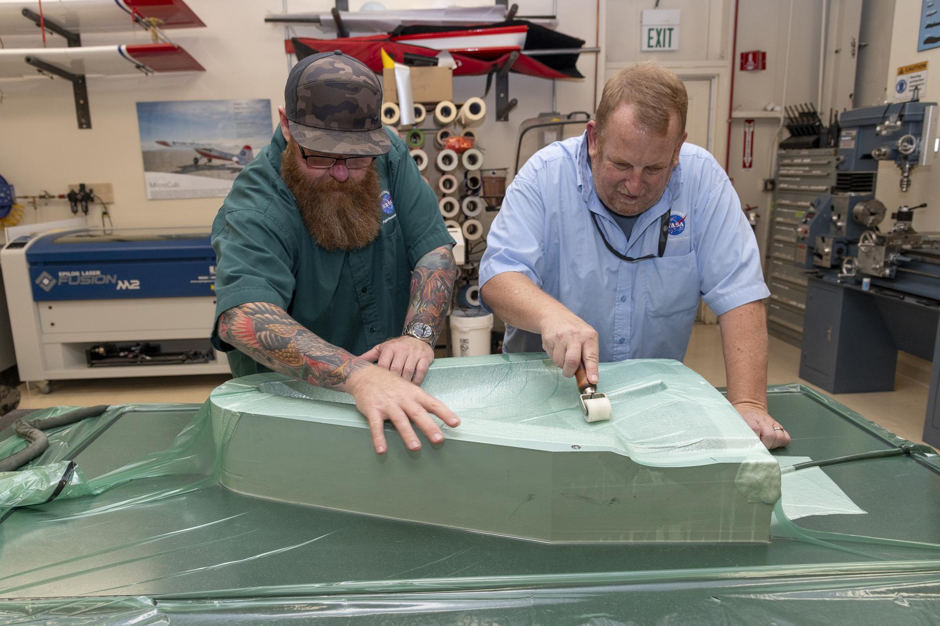
NASA Armstrong Updates 1960s Concept to Study Giant Planets

David Woerner

Tech Today: Cutting the Knee Surgery Cord

NASA, Industry Improve Lidars for Exploration, Science

NASA, Salisbury U. Enact Agreement for Workforce Development

NASA, Partners Select Universities for CubeSat Summer Program

NASA’s OSIRIS-REx Mission Awarded Robert Goddard Memorial Trophy

Partnerships that Prepare for Success: The Research Institution Perspective on the M-STTR Initiative

Astronauta de la NASA Marcos Berríos

Resultados científicos revolucionarios en la estación espacial de 2023
Science in space: march 2024.
Optical fibers are used on Earth and in space for applications in medicine, defense, cybersecurity, and telecommunications. Parabolic research showed that optical fibers produced in microgravity can be higher quality than those made in normal gravity, and the International Space Station provides a potential platform for commercial production of these fibers. The Production of Flawless Space Fiber ( Flawless Space Fibers-1 ) investigation is using the space station to demonstrate new manufacturing technology developed by Flawless Photonics to improve the quality and length of optical fiber produced in space.
Preliminary results have been promising. From mid-February to mid-March, the investigation manufactured a total of more than seven miles (11.9 km) of optical fiber. Eight of the runs (called draws) produced more than 2,200 feet (700 meters) of fiber, demonstrating that the results are repeatable. The investigation also drew more than 3,700 feet (1141 meters) in one day, surpassing the prior record of 82 feet (25 meters) for the longest fiber manufactured in space. Seven of the draws exceeded 2,296 feet (700 meters), demonstrating for the first time that commercial lengths of fiber can be produced in space. The space-drawn fibers are set to return to Earth soon for analysis of their quality.
These fibers are made using ZBLAN, a glass alloy made of zirconium, barium, lanthanum, sodium, and aluminum fluorides, each with different densities and crystallization temperatures. Its unique properties allow light to travel through a fiber over a broader range, providing more than ten times the capacity of traditional silica-based fibers and transmitting considerably more data over the same length of fiber. If fibers can be made long enough and of high enough quality, the increased efficiency of ZBLAN could translate into significant energy savings by reducing the need to boost the signal on long-distance transmissions.
However, when ZBLAN is drawn into fibers on the ground, crystals form that scatter signals and make the fiber brittle. Because crystals grow more slowly in microgravity, the approach is to cool drawn fibers before crystals have a chance to form. Microgravity also counters effects of sedimentation, convection, and buoyancy that limit the length and quality of fibers drawn on Earth. Manufacturers use drop towers to manufacture ZBLAN on Earth, but in-space manufacturing provides much more time to draw longer and eventually better fibers.

The Flawless Space Fibers investigation is sponsored by the ISS National Laboratory and involves support from the Luxembourg Space Agency, University of Adelaide in Australia, and NASA’s InSpace Production Applications (InSPA). InSPA advances sustainable, scalable, and profitable in-space manufacturing in low Earth orbit, working with the ISS National Lab to provide companies with access to the space station for demonstrating production of advanced materials and products for terrestrial applications. Flawless Space Fibers has achieved three of four goals for ZBLAN set by InSPA, including achieving 20 meters on a single run, repeating that amount on a separate draw, and scaling up to runs of commercial length. The analysis of fibers after return to ground is needed to determine whether the investigation meets InSPA’s fourth goal, producing fiber of ten times greater quality than on Earth.
Results may help reduce gravity-induced defects in optical glass products developed on Earth and advance in-space manufacturing models. The investigation also opens the door to creating other valuable specialty fibers in space.

NASA conducted early work processing ZBLAN in microgravity through Marshall Space Flight Center in the 1990s and early 2000s. Development of ZBLAN manufacturing on the space station began in 2014.
Other investigations that examined manufacturing ZBLAN optic fibers in microgravity include Optical Fiber Production in Microgravity ( Made In Space Fiber Optics ), which conducted the first privately funded ZBLAN fiber draw, Fiber Optic Production , and Fiber Optic Production-2 ( FOP-2 ), which first demonstrated repeated production of 20-meter lengths of fiber in microgravity. Another investigation, Fiber Optics Manufacturing in Space ( Space Fibers ), developed by FOMS Inc, first demonstrated a fully operational space facility for fiber manufacturing. 1
These efforts support commercial development of space and low Earth orbit and offer opportunities for development of next-generation technologies in space for applications on Earth.
John Love, ISS Research Planning Integration Scientist Expedition 70
Search this database of scientific experiments to learn more about those mentioned above.
1 Starodubov D, McCormick K, Dellosa M, Erdelyi E, Volfson L. Facility for orbital material processing. Sensors and Systems for Space Applications XI, Orlando, Florida. 2018 May 2; 10641106410T. DOI: 10.1117/12.2305830.
Discover More Topics
Latest News from Space Station Research

ISS National Laboratory
In Space Production Applications

Space Station Research and Technology

Fiber Lateral Stress Sensor Based on Michelson Interference and Optical Vernier Effect
Ieee account.
- Change Username/Password
- Update Address
Purchase Details
- Payment Options
- Order History
- View Purchased Documents
Profile Information
- Communications Preferences
- Profession and Education
- Technical Interests
- US & Canada: +1 800 678 4333
- Worldwide: +1 732 981 0060
- Contact & Support
- About IEEE Xplore
- Accessibility
- Terms of Use
- Nondiscrimination Policy
- Privacy & Opting Out of Cookies
A not-for-profit organization, IEEE is the world's largest technical professional organization dedicated to advancing technology for the benefit of humanity. © Copyright 2024 IEEE - All rights reserved. Use of this web site signifies your agreement to the terms and conditions.
Subscribe to the PwC Newsletter
Join the community, edit social preview.

Add a new code entry for this paper
Remove a code repository from this paper, mark the official implementation from paper authors, add a new evaluation result row, remove a task, add a method, remove a method, edit datasets, information rates of successive interference cancellation for optical fiber.
22 Mar 2024 · Alex Jäger , Gerhard Kramer · Edit social preview
Successive interference cancellation (SIC) is used to approach the achievable information rates (AIRs) of joint detection and decoding for long-haul optical fiber links. The AIRs of memoryless ring constellations are compared to those of circularly symmetric complex Gaussian modulation for surrogate channel models with correlated phase noise. Simulations are performed for 1000 km of standard single-mode fiber with ideal Raman amplification. In this setup, 32 rings and 16 SIC-stages with Gaussian message-passing receivers achieve the AIR peaks of previous work. The computational complexity scales in proportion to the number of SIC-stages, where one stage has the complexity of separate detection and decoding.
Code Edit Add Remove Mark official
Datasets edit.
Global Site
Breadcrumb navigation
Nec and ntt successfully conduct first-of-its-kind long-distance transmission experiment over 7,000km using 12-core optical fiber.
Tokyo, Japan, March 21, 2024 – NEC Corporation (NEC; TSE: 6701) and NTT Corporation (NTT) today announced that they have successfully conducted a first-of-its-kind transoceanic-class 7,280km transmission experiment using a coupled 12-core multicore fiber (*1), which consists of 12 optical signal transmission paths in a standard outer diameter optical fiber (0.125 mm). This achievement is expected to be a next-generation transmission infrastructure technology that will contribute to the realization of large-capacity optical networks, including future optical submarine cables.

With the spread of 5G globally and increased communications between data centers, international Internet traffic increased at an average annual rate of 30% from 2018 to 2022 (*2), and this trend is expected to continue. In order to meet the strong communication demand, there is a growing need to increase transmission capacity per optical submarine cable system in addition to increasing the number of optical submarine cables. Existing optical submarine cables use single-core fiber, which has a single optical transmission path called a core within a single fiber. In contrast, research and development is being conducted around the world to increase cable capacity by using multicore fiber, which has multiple cores to increase transmission capacity without changing the standard outer diameter of the fiber. NEC is currently engaged in a project to install a long-haul optical submarine cable system using two-core multicore fiber with two optical transmission paths.
Research Results
As more cores are added to an optical fiber with a standard outer diameter, crosstalk occurs when optical signals leaking from a core interfere with optical signals in adjacent cores, resulting in interference, which deteriorates the quality of mutual communications. Especially in long-distance transmission, in addition to the seriousness of crosstalk, it becomes difficult to receive transmitted signals accurately due to the non-uniformity of delay and loss between optical signals. NEC and NTT have developed the following technologies to address these issues.
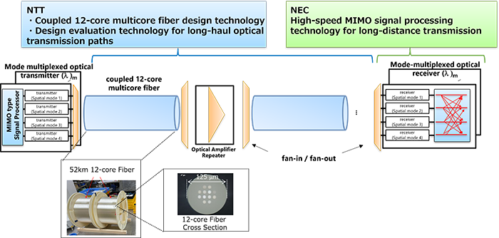
1. Development of an algorithm by NEC for demodulation of received signals using Multiple Input Multiple Output (MIMO) technology
Although MIMO technology is commonly used to separate multiple interfering radio signals, the scale of MIMO signal processing that has been put into practical use in existing optical communications is limited to two-polarization multiplexed signals. In addition, multicore fiber with many cores requires more extensive signal processing because the optical signals are further multiplexed. In addition, the random occurrence of crosstalk in long-distance transmission is an issue that must be addressed. NEC has now developed an algorithm for long-distance transmission and applied it to 24 x 24 MIMO (12 cores x 2 polarizations), enabling accurate separation and demodulation of high-speed received signals.
2. Development of a coupled 12-core multicore fiber optical transmission line by NTT
In long-haul optical communications using multicore fiber, when non-uniform delays and losses occur in the propagation between multiplexed optical signals, the circuit resources required for MIMO signal processing during reception increase, making implementation and realization difficult. In addition, non-uniformity in propagation loss greatly limits the distance that can be transmitted. In this study, NTT has developed design technologies for coupled multicore fiber and optical input/output devices (connecting fan-in/fan-out) that can reduce the effects of non-uniformity among signal delay and loss, as well as optical transmission line design evaluation technologies for long-haul applications. Combining these technologies, NEC and NTT conducted long-distance transmission experiments over 7,280km, assuming a transoceanic-class optical submarine cable, and succeeded for the first time in the world in accurately demodulating 12-spatially multiplexed optical signals offline.
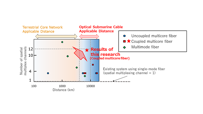
Future Developments
The two companies will further advance the research and development of these technologies with the aim of commercializing them as a long-haul, high-capacity optical submarine cable system and terrestrial core network system that will contribute to the realization of a high-capacity optical transmission infrastructure in the IOWN® (*3) concept and Beyond 5G/6G era in the 2030s. NEC and NTT will present the results as a highly scored paper at the Technical Conference of OFC 2024, the world's largest event on optical communications (March 24 to March 28, 2024, at the San Diego Convention Center in California, USA).
Acknowledgements
A part of these results were obtained through a contract for research (JPJ012368C01001) sponsored by the National Institute of Information and Communications Technology (NICT) in Japan.
- * IOWN® is a trademark or registered trademark of NTT Corporation
- (*1) Coupled multicore fiber: An optical fiber in which signals transmitted in each core are separated and demodulated by post-processing on the premise that optical signals leaking from multiple optical transmission paths (cores) in the fiber interfere with and influence each other.

About NEC Corporation NEC Corporation has established itself as a leader in the integration of IT and network technologies while promoting the brand statement of “Orchestrating a brighter world.” NEC enables businesses and communities to adapt to rapid changes taking place in both society and the market as it provides for the social values of safety, security, fairness and efficiency to promote a more sustainable world where everyone has the chance to reach their full potential. For more information, visit NEC at https://www.nec.com .
IMAGES
VIDEO
COMMENTS
Optical Fibers and Their Applications 2020. DOI: Edition: Optical Fibers and Their Applications 2020, Proc SPIE 11456, 2020. Publisher: SPIE - International Society for Optics and Photonics ...
RSS Feed. Fibre optics and optical communications is the use of thin strands of glass for sending information encoded into light over long distances. Total internal reflection prevents light ...
Optical Fiber Technology: Materials, Devices, and Systems is a new cutting-edge journal designed to fill a need in this rapidly evolving field for speedy publication of regular length papers. Both theoretical and experimental papers on fiber materials , devices , and system performance evaluation and measurements are eligible, with emphasis on ...
In this report, we focus on the first three common types of optical fibers. As a common application of the fibers, these can be used in fiber lasers to create and amplify a narrow intense beam of coherent and monochromatic light. Fabrication of optical fiber involves three stages such as the preform formation.
From gigabits to terabits of data transmission, Fiber optic communication is the most perfect as well as smartest choice. This sort of communication is used in the transmission of voice, video, images, and data over great distances, local area networks (LAN) or computer systems. The fiber optic communication system uses light-wave technology to transmit information over the fiber by converting ...
Fiber-based micro-endoscopes are minimally invasive, but 3D imaging is limited by the need for bulky optical elements or rigid fibers. Here, the authors demonstrate holographic imaging through ...
Search for more papers by this author. Timothy D. Wilkinson, Timothy D. Wilkinson. Department of Engineering, University of Cambridge, Cambridge, CB2 1TN UK ... However research on fiber-optic probes started 30 years ago, and few types of optical fiber probes reached the commercialization stage such as fiber Bragg gratings that are used in real ...
This paper represents a comprehensive exploration of mathematical modeling and analysis in the context of fiber communications, with a specific focus on optimizing performance and efficiency. Positioned at the vanguard of innovation within the field of nonlinear optics, this research stands as a pioneering effort, venturing into uncharted territory by comprehensively examining soliton ...
Optical multimode fiber (MMF) has emerged as an ideal tool for studying transmission through complex media attributed to its high throughput with low loss, defined degrees of freedom, small form ...
In future, fiber optics is projected to play a significant role in this expansion. According to a report conducted by Research and Markets, the fiber optic market's compound annual growth rate might reach 8.5 percent by 2025, implying that more businesses will be interested in the solutions offered by this technology.
In this paper, we present phase-separated alumina-silica glass-based Er 3+-doped optical fibers made by a modified chemical vapor deposition (MCVD) process in combination with a solution doping (SD) technique.The fibers exhibited better optical performance than other silica-based host glasses—both in terms of spectral broadening and flattening of the gain spectra in the C band (1530-1560 ...
Fiber-Optic Michelson Interferometer (FOMI) The working principle of the FOMI is analogous to FOMZI.[13e] The guided light in the fiber core is split to propagate in reference and sensing ber arms. However, the guided light is re ected at fi fl the end of each arm by mirrors to recombine in the light launch-ing ber.
Increased production and further use of composite materials in oilfield applications have brought about the foremost consideration of intelligent structures for sensing and monitoring applications. 1,2 Fiber optic sensors were excellent candidates for non-destructive evaluation techniques, detecting possible damage, and measuring mechanical properties of pipework. 3 The implementation of these ...
the most important aspects of this paper. 2. Optical Fiber Sensors An optical fiber is a cylindrical dielectric waveguide, where both the core and the cladding are composed of glass or plastic, and the surrounding coatings used to protect the optical fiber are made of acrylate or polyimide materials. Optical fibers can be multi-mode or ...
Nanoparticle-doped optical fibers, investigated first as fiber lasers and fiber amplifiers, have gained tremendous interest over the past few years as fiber sensors. One of the main interests of such fibers relies on the ability to develop a distributed sensor, allowing real-time measurement with multiplexed architecture. To go beyond the actual proof of concept, we discuss in this perspective ...
The current worldwide organizations request quicker, safer and bigger limit communication frameworks for their organization activities. Fiber optic innovation is relied upon to have a significant impact in this development. From medical services frameworks to the marine climate, fiber optic cable is ending up being a vital segment of mechanical foundation. Fiber optic link gatherings are ...
Optical fiber sensors have been studied, developed, and already used in the industry for more than 50 years due to their multiplexing capabilities, lightweight design, compact form factors, and electromagnetic field immunity. The scientific community continuously studies new materials, schemes, and architectures aiming to improve existing technologies. Navigating through diverse sensor ...
Figure 1 illustrates the annual number of research papers related to FP fiber optic sensors from 1999 to 2023. As observed, there has been a consistent and steady increase in the number of publications in this field in recent years. This upward trend clearly indicates that FP fiber optic sensors have gained significant attention from the ...
The diameter of commonly used optical fiber is 125 μm and the diameters of advanced multi-material multi-functional fibers are a few hundred microns, making the whole fiber-based sensors occupy diameters less than 1 mm. In addition, the fibers are flexible and bendable, making them ideal for attaching to curved surfaces.
This paper summarizes the application of advanced optical fiber sensors in lithium-ion batteries and energy storage technologies that may be mass deployed, focuses on the insights of advanced optical fiber sensors into the processes of one-dimensional nano-micro-level battery material structural phase transition, electrolyte degradation ...
In this paper, the optical fiber sensing ring of the transformer designed is a flexible structure, which can be directly wound on the spot according to the shape of the measured conductor, thereby avoiding the work of disassembling the measured conductor. ... Hao Z R, Wang Q, Da J P, et al. Research and application of all-fiber optic current ...
Optical fibers are used on Earth and in space for applications in medicine, defense, cybersecurity, and telecommunications. Parabolic research showed that optical fibers produced in microgravity can be higher quality than those made in normal gravity, and the International Space Station provides a ...
In this paper, an ultra-sensitive optical lateral stress sensor with the Optical Vernier effect (OVE) is successfully fabricated, and its feasibility is also experimentally demonstrated. The fundamental structure of this sensor is an optical fiber Michelson Interferometer (MI) based on an optical coupler. One arm of the MI is built up by the single mode fiber (SMF) with a well-cleaved end. The ...
Stay informed on the latest trending ML papers with code, research developments, libraries, methods, and datasets. ... of joint detection and decoding for long-haul optical fiber links. The AIRs of memoryless ring constellations are compared to those of circularly symmetric complex Gaussian modulation for surrogate channel models with ...
Currently, fiber optic transmissions rely on the C- and L-bands. But the research team figured out a way to send stable data through the co-existing E- and S-bands for a major speed boost.
Fiber optics will be the backbone for 5G, 5.5G, 6G, and beyond. Additionally, the miniaturization of fiber optic components and the development of flexible fibers will unlock new applications in Internet of Things (IoT) devices. The importance of fiber optics for fast data transmission is clear, but there's still so much more this technology ...
Existing optical submarine cables use single-core fiber, which has a single optical transmission path called a core within a single fiber. In contrast, research and development is being conducted around the world to increase cable capacity by using multicore fiber, which has multiple cores to increase transmission capacity without changing the ...