Bipolar Transistors
Ieee account.
- Change Username/Password
- Update Address

Purchase Details
- Payment Options
- Order History
- View Purchased Documents
Profile Information
- Communications Preferences
- Profession and Education
- Technical Interests
- US & Canada: +1 800 678 4333
- Worldwide: +1 732 981 0060
- Contact & Support
- About IEEE Xplore
- Accessibility
- Terms of Use
- Nondiscrimination Policy
- Privacy & Opting Out of Cookies
A not-for-profit organization, IEEE is the world's largest technical professional organization dedicated to advancing technology for the benefit of humanity. © Copyright 2024 IEEE - All rights reserved. Use of this web site signifies your agreement to the terms and conditions.
Thank you for visiting nature.com. You are using a browser version with limited support for CSS. To obtain the best experience, we recommend you use a more up to date browser (or turn off compatibility mode in Internet Explorer). In the meantime, to ensure continued support, we are displaying the site without styles and JavaScript.
- View all journals
- My Account Login
- Explore content
- About the journal
- Publish with us
- Sign up for alerts
- Open access
- Published: 22 June 2022
Organic bipolar transistors
- Shu-Jen Wang 1 na1 ,
- Michael Sawatzki 1 na1 ,
- Ghader Darbandy ORCID: orcid.org/0000-0003-0537-3984 2 ,
- Felix Talnack ORCID: orcid.org/0000-0002-7472-906X 3 ,
- Jörn Vahland 1 ,
- Marc Malfois ORCID: orcid.org/0000-0001-5231-1896 4 ,
- Alexander Kloes ORCID: orcid.org/0000-0002-6485-1512 2 ,
- Stefan Mannsfeld ORCID: orcid.org/0000-0003-0268-519X 3 ,
- Hans Kleemann ORCID: orcid.org/0000-0002-9773-6676 1 &
- Karl Leo ORCID: orcid.org/0000-0003-3313-1843 1 , 3
Nature volume 606 , pages 700–705 ( 2022 ) Cite this article
20k Accesses
35 Citations
203 Altmetric
Metrics details
- Electrical and electronic engineering
- Electronic and spintronic devices
- Electronic devices
Devices made using thin-film semiconductors have attracted much interest recently owing to new application possibilities. Among materials systems suitable for thin-film electronics, organic semiconductors are of particular interest; their low cost, biocompatible carbon-based materials and deposition by simple techniques such as evaporation or printing enable organic semiconductor devices to be used for ubiquitous electronics, such as those used on or in the human body or on clothing and packages 1 , 2 , 3 . The potential of organic electronics can be leveraged only if the performance of organic transistors is improved markedly. Here we present organic bipolar transistors with outstanding device performance: a previously undescribed vertical architecture and highly crystalline organic rubrene thin films yield devices with high differential amplification (more than 100) and superior high-frequency performance over conventional devices. These bipolar transistors also give insight into the minority carrier diffusion length—a key parameter in organic semiconductors. Our results open the door to new device concepts of high-performance organic electronics with ever faster switching speeds.
Ion buffering and interface charge enable high performance electronics with organic electrochemical transistors

Monolithically integrated high-density vertical organic electrochemical transistor arrays and complementary circuits

Thin-film transistors for large-area electronics
Organic field-effect transistors (FET) were first reported in 1986 and have shown impressive improvements in the past two decades 4 , 5 , 6 , 7 , 8 , 9 , 10 , 11 . Nevertheless, they are still restricted to the low-to-medium megahertz range, which does not allow broad application 12 , 13 , 14 . The substantially lower charge carrier mobility in organic semiconductors (OSCs) compared with their inorganic counterparts is a limitation to the performance of organic transistors. Reducing the length of transistor channels is an effective strategy for improving the operational speed of the device, as shown both in FET 13 , 14 and other device concepts such as organic permeable-base transistors 11 , 15 . However, other factors, such as contact resistance and overlap capacitances, often limit further improvement of operational frequencies 16 , 17 .
A device that offers both low capacitance and contact resistance is the bipolar junction transistor. Although they have disadvantages with regard to miniaturization and process integration, bipolar transistors possess substantially higher operational speeds than comparable field-effect devices 18 . However, organic bipolar junction transistors (OBJTs) have not yet been realized, mainly because they rely on minority carrier diffusion through a thin and precisely doped base layer. Most studies have addressed exciton diffusion, which dominates owing to the weak dielectric screening in organic compounds 19 , 20 . Majority carrier diffusion length in fullerenes has been estimated to be on the centimetre scale, raising interesting questions about carrier diffusion physics in OSCs 21 , 22 . Charge carrier minority diffusion lengths have remained unexplored in OSC materials until now. In comparison to exciton diffusion, they can be expected to be in the nanometre range, at least for typical disordered organic films 23 , 24 , 25 .
Here, we realize an OBJT based on crystalline films of n- and p-type doped rubrene. In contrast to common furnace-grown single crystals, these films are made directly on the surface of a substrate and are thus compatible with mass production. We have demonstrated previously the excellent device potential of such highly ordered films by showing record-high vertical charge carrier mobilities that enabled ultrafast diode devices to operate in the gigahertz range 26 . Here we demonstrate that OBJTs based on crystalline rubrene thin films provide a promising route towards gigahertz organic electronics. Numerical simulations clarify the principles of transistor operation and present routes towards further optimization. A careful analysis of the device operation enables the direct measurement of minority carrier diffusion length in any OSC.
A key challenge in realizing an organic bipolar transistor is to find a suitable material and a device configuration that (1) allow both n- and p-type doping; (2) have sufficiently high (more than 1 cm 2 V −1 s −1 ) mobility allowing for balanced hole and electron transport, giving hope that the, so far unknown, minority carrier diffusion lengths are high enough to allow the carriers to travel through the base layers; and (3) allow a sufficiently thin base held at a defined potential to allow emitter–collector current control. We made use of the highly crystalline rubrene thin-film crystals with n- and p-type doping for the construction of this OBJT and analyse its operation experimentally and theoretically (for details of materials development and characterization, see Methods ).
Development of OBJTs
Using these highly crystalline doped films, we produced an OBJT. The device geometry is shown in Fig. 1a–c , featuring a vertical stacking of a rectangular emitter electrode at the bottom, a finger-like structured base electrode in the middle and a rectangular collector (top) electrode. The distancing between adjacent fingers of the base electrode and the width of each base finger itself are crucial, as discussed below. The final device is of pnp type, with an n-doped base, as we expect the p-type minority diffusion length to be higher owing to higher mobility. As is common for organic diode-like devices 26 , intrinsic films are added in between p- and n-doped films to improve reverse leakage behaviour, ending up with a pinip structure. Emitter and collector electrodes are made from gold to facilitate efficient hole injection, whereas the base electrode consists of aluminium for better electron injection. A thin film of n-doped C 60 is added on the emitter side of the base electrode to further facilitate electron injection. Additional layers of intrinsic and weakly doped material can be added on top of the base electrode to minimize base–collector leakage.

a , Vertical stack configuration of the OBJT. b , Definition of active and parasitic currents and lateral geometric parameters in the OBJT. c , The OBJT device under a polarized microscope. Scale bar, 100 μm. d , Transfer characteristics of the OBJT device with blocking layers deposited on top of the base electrode for different V CE : solid lines give the absolute collector current I C , dashed lines give added current ∆ I C = I C − I C0 . e , The corresponding differential amplification for the device in d . f , Definition of the biasing and measurement setup for all OBJT curves and representation of the equivalent circuit of the OBJT containing active and parasitic components analogous to the currents defined in b : D B1 , direct base–collector diode with I BC leakage current; D B2 , direct base–emitter diode with I BE leakage current; R CE , direct emitter–collector overlap with I C0 output off-current. g , Transfer characteristics of the OBJT device without blocking layers deposited on top of the base electrode at different V CE : solid thick lines, absolute collector current I C ; dashed lines, added current ∆ I C = I C − I C0 ; solid thin lines, absolute direct current amplification. h , Absolute and area-normalized capacitance of an individual rubrene-based pin (input) diode at different biasing conditions and varying measurement frequencies. The active area is 100 × 100 μm 2 . i , Transition frequency estimation from transconductance.
It might seem self-evident to use the triclinic crystal phase of rubrene for bipolar junction transistors owing to their higher vertical charge carrier mobility, facilitating a more efficient vertical diffusion through the base layer. However, in addition to vertical transport, the n-doped rubrene layer of the base should be an area of equipotential with the metallic base electrode, which requires a high lateral conductivity. The distance between adjacent metallic base electrodes is the defining geometric parameter for this device concept and is in the range of micrometres. Therefore, orthorhombic crystals are used here successfully for OBJT because of their isotropic charge transport properties—transistor operation using triclinic crystals was not observed.
We first look at a device based on orthorhombic spherulite crystals with more blocking layers deposited on top of the base electrode (Fig. 1d,e ). The base–emitter diode, the base–collector diode and the emitter–collector pinip structure are first investigated separately to check functionality at component level (Extended Data Fig. 1a ). The input and output components function individually as diodes, with distinguishable forward and reverse behaviour. The base–collector diode possesses a substantially lower forward current than the base–emitter input diode owing to the extra blocking layers on top of the base electrode. However, the reverse current and forward leakage on both sides of the base are almost identical. This is a sign that the leakage current is governed by lateral leakage paths rather than the current going through the pin diodes. As expected, the direct current from emitter to collector is fully symmetric (see impedance measurements in Extended Data Fig. 2 ). However, this current is substantially higher than the current through the diodes themselves. The high emitter–collector current can be explained partly by the simple electrode design, which creates a large area of parasitic overlap between emitter and collector. It is possible to reduce the emitter–collector current by structuring the electrode. A discussion about the optimal geometric configuration based on simulations is given in the next section. Our main focus here is on the base region to enable the operation of the OBJT.
Figure 1d shows the transfer curve of the full OBJT (the electrode gap in base electrode is 12 µm), that is, the emitter (output) current over the base (input) current at different emitter–collector voltages. It is obvious that the absolute value of the emitter current is large and barely changes throughout the measurement. Only at high base currents is a slight increase noticeable. This is caused by the emitter–collector leakage current discussed above. This leakage current can be seen as a constant shunt R CE in parallel with the output of the device (an equivalent circuit is presented in Fig. 1f ). Thus, the real output of the transistor reflects the change in collector current (also shown in Fig. 1d ) controlled by the base current. A steady increase in output current over input current is visible, with a steep increase at low and high base currents and a substantially shallower slope in the medium current regime. The general behaviour is similar for all applied emitter–collector voltages, albeit shifted by an absolute current. Focussing on the largest V CE of −8 V, the added collector current surpasses the input base current only until a base current of 15 μA.
Figure 1e shows the differential signal amplification ∂ I C /∂ I B . It is as large as 100 at a low base current, clearly proving transistor action, and then decreases steadily with increasing base current. The loss of differential amplification occurs at I B = 2 μA. This decrease in differential amplification can be understood from the geometry of the device: an illustration of the current paths is given in Fig. 1b . In addition to the already mentioned current path through R CE , leading to a large I C0 , the top and bottom diodes of the transistor can be split into two parts. First, a large part of each diode is defined by the area of direct overlap of the base and the collector or emitter electrode. This region contributes only to the leakage current and does not contribute to transistor operation. The leakage current through the base–collector diode D B1 is denoted as I BC and the leakage current through the base–emitter diode D B2 as I BE . Second, a smaller part is defined by the area around the base electrode fingers in which the base potential is present. This distance is given by the base reach L R . The corresponding area is marked in Fig. 1b . Only the second part (current I B,S ) can contribute to the modulation of the collector current in the form of I C,S . The equivalent circuit of this configuration is shown in Fig. 1f . The amplification of the transistor component starts to saturate at higher base currents owing to the exponential increase in input current through the parasitic parts of the input diode such that differential amplification cannot be maintained at higher base current. The measured differential amplification is therefore not an intrinsic property of the transistor but a property of the device functioning as a circuit.
The blocking layers deposited on top of the base electrode aimed at suppressing leakage current from the parasitic diode D B1 can, however, also block part of the channel next to the base electrode fingers that would contribute to the transistor operation due to the geometry of thermal evaporation through shadow masks. A balance must be found between the configuration of blocking films and electrode geometry. We also investigated a device based on orthorhombic platelet crystals without the use of blocking layers on top of the base electrode, the current–voltage ( IV ) characteristics of the device are shown in Fig. 1g . The transistor operation of the device at low currents is reduced, because the changed biasing of the base and the resulting change in parasitic current of the diode D B1 overcompensate for any diffusion-based amplification. However, at high base currents, the output collector current is increased substantially, and the transistor clearly shows large-signal amplification, although only moderate values. We would like to note that the unstable behaviour at high base current is probably caused by the high current density in the device, which is close to the onset of self-heating effect. Therefore, both differential and absolute current amplification can be observed in our OBJT devices based on doped rubrene crystals.
TCAD simulations of OBJTs
Technology computer-aided design (TCAD) simulations are performed to obtain a better understanding of the charge transport in the OBJT device and design rules for optimization of the device geometry. The simulations are based on the device stack that showed large-signal amplification as shown in Fig. 1g . The fabricated devices and experimental data are taken as a reference to calibrate the TCAD simulator. The IV characteristics of the individual components (base–emitter diode and emitter–collector structure) show good agreement between the calibrated simulation results and measured data as shown in Fig. 2a , thus confirming the viability of the device operation. On the basis of the calibrated TCAD, electrostatic potential, electric field, carrier density and the current, distributions can be simulated and extracted for different bias conditions and geometries. As an example, Fig. 2b shows the current density distribution in the OBJT. The lateral electric field distribution between two adjacent base fingers is shown in Fig. 2c .

a , Congruence of simulation and measurement on the basis of the experimental data from Fig. 1g . The simulation is tuned to reproduce IV characteristics of the emitter–collector and emitter–base (inset) individually. b , The geometry and current density distribution for an exemplary configuration of the OBJT as given by TCAD simulations. c , Field strength of the internal electric field in a lateral direction for different distances between adjacent base electrodes at V BE = V CE = −3 V. The inset shows a close-up view of the panel for clarity. d , Simulated maximum differential amplification with different widths of the base electrode L B . e , Simulated maximum differential amplification with hypothetical lateral offset between the end of the base electrode and the start of the emitter electrode L BE . f , Simulated maximum differential amplification with different distances between adjacent base electrodes L BB (all other parameters were kept constant in each set of simulations). The insets show the geometry of L B , L BE and L BB in the OBJT device. The parameters used are summarized in Supplementary Table 1 .
The simulation provides an insight into a key parameter of the transistor: the finger design of the base electrode. The length required for the field to drop from its maximum value to almost zero can be interpreted as the base reach L R . For an electrode distance of more than 25 μm, the lateral field is close to zero for an important part of the device, causing a large initial off-current that is not controllable by the base current. On the basis of the simulation, a base-to-base distance of 5 μm to 10 μm seems to be optimal.
Figure 2d shows the impact of the size and arrangement of the base electrodes on amplification. When the width of the base electrode is reduced from 25 μm to, theoretically, 0 μm (this is equivalent to no direct overlap between base, emitter and collector), the maximum amplification increases substantially, as the part of the base current that does not contribute to amplification decreases, whereas the controllable collector current remains the same. However, a base overlap of 0 μm is impossible to achieve for technological reasons. By contrast, a negative overlap in the sense of a spacer/gap between the end of the base and the beginning of the emitter can be achieved. Figure 2e shows the resulting amplification for such configuration. The amplification is reduced as expected as the important edge area near the base electrode is now substantially less involved in the transport. However, the reduction is comparably modest for a gap length of 1 μm. This degree of alignment precision would be achievable with advanced stencil lithography techniques.
Finally, the distance between adjacent base electrodes is varied, as shown in Fig. 2f . Surprisingly, the amplification increases slightly for increased distances between adjacent base electrodes, although a saturation is seen above 50 μm. This is because, although the lateral field is close to zero far from the base (Fig. 2c ), a small amount is still contributing to the output current. However, the off-current is also increased when the distance between bases is increased because the emitter–collector overlap increases simultaneously (Fig. 2f ). Therefore, there is a trade-off between the current amplification and the off-current when designing the base electrode.
Overall, the simulations confirm the operation of the OBJTs with differential as well as large-signal amplification. Furthermore, they give clear design guidelines how to further improve the devices.
Operation speed of OBJTs
With a total device thickness of approximately 1 µm and a high vertical mobility of approximately 3 cm 2 V –1 s –1 , OBJTs seem well suited for high-frequency operation. The most important dynamic performance parameter for any kind of transistor is the unity-gain cut-off frequency. A direct measurement of this quantity requires sufficient large-signal amplification and stability of operation. Unfortunately, in our OBJTs, we obtain large-signal amplification only at the highest applied bias, which results in unstable behaviour (Fig. 1g ). Still, we reasonably estimate the maximum speed of operation by evaluating the resistor–capacitor time of the system. Similar to the calculations done for FET, it is possible to estimate the maximum speed of operation in the form of the transition frequency from static properties using:
where g m and C denote the transconductance of the transistor and the capacitance, respectively. The transconductance describes the change in output current with input voltage. In case of the OBJT, it can be written as:
Because the output current ( I C ) is linked to the input current ( I B ) through the amplification ( β ), the transconductance is defined by the differential conductance of the input diode. Similarly, the defining capacitance is given by the input diode, assuming diffusion through the base is sufficiently fast, the transition frequency is seemingly limited only by the properties of the input diode. On the basis of the results obtained from the simulations, one goal is to reduce the direct base current as much as possible, which would reduce conductance of the input diode. However, the amplification of the device would increase accordingly, leaving the g m constant. A direct transition frequency measurement is challenging for OBJTs owing to the parasitic diodes that influence the phase of small signal measurements. Nevertheless, the high degree of agreement between the direct transition frequency measurements and the transconductance/capacitance estimations in the literature allow us to estimate the frequency response of our OBJTs 13 , 14 , 27 . For the device shown in Fig. 1g , the resulting transconductance is as high as 0.1 S (Fig. 1i ), in the range in which devices show amplification, whereas the capacitance is around 10 pF (Fig. 1h ). This results in a transition frequency of 1.6 GHz, which is similar to the speed of operation found for the single, rubrene-based diodes 26 and hence provides a significant step (10–40×) above the current state of the art of organic transistors 12 , 14 . Two reasons for the superiority of the OBJT are (1) highly crystalline films that feature improved mobilities compared with most OSCs and (2) the ultralow capacitance of devices associated with the vertical bipolar junction transistor design. In addition, limitations to contact resistance are less prominent here, because all the metal–OSC interfaces are doped by default and do not limit injection, proven by the space-charge-limited current analysis-like behaviour in rubrene pip devices.
Minority carrier diffusion length
The working principle of the OBJT is based on the diffusion of minority carriers (holes) through the base (n-doped film). In an ideal device, the diffusion length could be calculated directly from the doping concentrations, the width of the base layer and the resulting amplification. However, as discussed, the amplification measured here does not represent the intrinsic amplification of the transistor itself but of the device as a circuit. Nevertheless, the observation of amplification proves the diffusion of minority carriers through the base, with a minority diffusion length of at least 20 nm for devices with 1 wt% of base doping. In addition, we conducted experiments for which we varied the properties of the doping and structure of the base. Consistent with the inorganic bipolar junction transistor theory, both an increase in base doping from 1 wt% to 5 wt% and an increase in base layer thickness substantially reduce current amplification. The strong dependency of OBJTs on the base thickness and doping concentration is associated with the minority carrier diffusion operation, which is in stark contrast to organic permeable-base transistor operation based on most carrier transport. It is possible to estimate the diffusion length from devices with different base thickness when all remaining parameters remain identical. Figure 3 shows the OBJT operation based on a new set of devices with improved electrode geometry, reducing the area of electrode overlap that does not contribute to the transistor operation. The reduction in the parasitic electrode overlap area improves transistor performance, which is in line with the TCAD simulations (Fig. 3d ). On the basis of these measurements, the diffusion length for holes through the n-doped rubrene is estimated, by fitting the classical bipolar transition relation \(\beta \propto {\rm{\coth }}\left(\frac{W}{{L}_{{\rm{D}}}}\right)\) together with the calibrated TCAD simulation, to be roughly 50 nm, showing excellent agreement with experimental results and minority-carrier-dominated device operation by using an input diffusion length of 50 nm (Fig. 3d–f and Extended Data Figs. 1 and 3 ). Exciton diffusion lengths in the micrometre range found in photoexcitation experiments on single crystals of rubrene 28 indicate fundamentally different mechanisms governing the transport and relaxation of minority holes. Considering the high structural order of rubrene crystals after doping, the recombination processes are probably caused by the slight widening of the density states. Our OBJT device provides a tool to obtain direct access to the physical properties of minority carrier diffusion in similarly high mobility OSC systems, opening the possibility to investigate fundamental questions about mechanisms of minority recombination in OSCs.

a , b , Differential amplification of OBJTs with different base layer thicknesses ( a ) and tetrakis(hexa-hydropyrimidinopyrimidine)ditungsten(II) (W 2 (hpp) 4 ) doping concentrations ( b ). c , d , Optical microscope images of different OBJT electrode designs ( c ) and corresponding device differential amplification curves ( d ). The solid lines denote experimental results and the hollow symbols denote TCAD simulation results. Scale bars, 100 μm. The device has a base thickness of 20 nm with 1 wt% W 2 (hpp) 4 doping concentration. e , Normalized differential amplification as a function of effective base width and doping. The effective base width is the base thickness minus the space charge length (2LSCL is approximately 10 nm determined from TCAD simulation and electrical characterization). The differential amplification was taken at a base current of 10 −5 mA, for which there is a good agreement between the TCAD and experiment results. The error bars denote the standard error of the mean by averaging over five devices prepared in a single run. The red curve is a coth fit with minority diffusion length of 50 nm. f , TCAD-simulated hole current density as a minority carrier (top) and electron current density (bottom) in the n-doped base layer.
In summary, we demonstrate a functional OBJT, delivering a missing piece of the puzzle on the organic transistor roadmap. Our OBJTs, based on highly crystalline rubrene thin-film crystals, not only provide a promising route towards ultrahigh-frequency organic transistors, but also allow the study of important fundamental physical parameters such as the minority carrier diffusion length, estimated to be around 50 nm for a doping concentration of 5 wt% for rubrene crystals. We believe that our results pave the way for next-generation high-performance organic electronic devices and provide a tool for understanding carrier diffusion physics in high mobility OSCs.
Details of rubrene thin-film crystal development
Growth procedures.
The general process for growing thin-film crystals of rubrene was described in refs. 29 , 30 . In Extended Data Fig. 4a,b , we show the fabrication process for rubrene thin-film crystals and types of rubrene thin-film crystal phase upon doping, respectively. A thin layer of amorphous rubrene is deposited on a substrate by vacuum deposition and then annealed in a nitrogen atmosphere to initiate crystal growth. Different crystal phases are possible depending on surface properties and heating temperature. The three most common types of crystal are triclinic spherulites, orthorhombic spherulites and orthorhombic platelets (Extended Data Fig. 4b ). Triclinic crystals start to form from approximately 120 °C and are the most robust and reproducible of the common crystal phases. Previously, we have shown the improved properties of triclinic films in gigahertz diodes 26 . Although the vertical mobility in these triclinic films is high, lateral transport is inefficient because of the strongly branched nature of these films. Orthorhombic crystals are the main focus in most publications owing to the isotropic charge transport properties originating from its herringbone molecular packing with ideal wavefunction overlap 31 , 32 , 33 . The spherulitic configuration of the orthorhombic packing grows at higher temperatures above 170 °C without strong branching, and can be identified easily under a polarized microscope by straight rays fanning out from the individual centre of each crystallite. Orthorhombic platelets are the most difficult phase to be created consistently. Heating at 150 °C to 170 °C commonly results in a few single crystals or clusters of crystals distributed over the surface. A previous study showed that a uniform and surface-covered distribution of platelet crystals can be achieved by the introduction of a sublayer with appropriate glass transition temperature 34 . Here we use 5 nm of 4,4′-cyclohexylidenebis[ N , N -bis(4-methylphenyl)benzenamine] (TAPC), resulting in successful crystal growth on glass and silicon substrates as well as structured metal and indium-tin-oxide electrodes 35 .
Epitaxy and doping
To make an OBJT, we need to control the total thickness of the crystal and the sequence of doped films precisely to realize complex device stacks. We introduced doping using coevaporation into initial seed and epitaxially grown layers. The maximum concentration of dopant that allows reproducible crystallization of the seed is below 2 wt% for both the p-type and n-type dopants studied here. Films added using epitaxy can be doped at substantially higher concentrations without any great changes in morphology visible by polarized microscopy. However, a change in surface properties can be seen in atomic force microscopy (AFM) measurements. The plateaus intermixed with line and screw dislocations that are described in ref. 36 are visible for the undoped crystals but gradually change into a more granular surface with fewer distinct features when doping is introduced (Extended Data Figs. 5 and 6 ).
Structural analysis
GIWAXS measurements of thin films of seed and bulk material show a change in the molecular packing of the rubrene crystals upon doping. Two-dimensional (2D) plots of the scattering image (Extended Data Fig. 7a ) prove the high degree of crystallinity, especially of the orthorhombic platelet form. The widths of the corresponding scattering peaks indicate the degree of disorder along the corresponding axis. Here the in-plane signal ( xy ) corresponds to the a - and b -crystal axis of the rubrene unit cell, which is important for lateral transport. The out-of-plane axis is defined by the c axis, relevant for the vertical transport. Extended Data Fig. 7b shows the change in peak width in both directions depending on the doping concentration and type. Peaks are substantially broader in the out-of-plane direction, which can, however, be attributed partly to the way the data are analysed (see the ‘ GIWAXS analysis’ section and Extended Data Fig. 8 ). The relative change is, however, more important than the absolute values. The in-plane data behave as expected in that a higher doping concentration results in a broadening of peaks, indicating a reduction in molecular order. Introduction of the n-dopant tetrakis(hexahydropyrimidinopyrimidine)ditungsten(II) (W 2 (hpp) 4 ) has a stronger impact than the p-dopant 1,3,4,5,7,8-hexafluorotetracyanonaphthoquinodimethane (F 6 -TCNNQ) when both films are doped to the same weight concentration. The introduction of dopant to the bulk part of the film generally increases the disorder in the film for both platelet and spherulitic samples (Extended Data Fig. 7b ). The out-of-plane axis behaves differently. Here doping of the seed shows a strong change in peak width, suggesting that integration of the dopant into the structure during seed crystallization is influencing mainly the c direction. Integration of dopant into the bulk films gradually increases the peak width, similar to the in-plane behaviour. However, the relatively stronger impact of the n-dopant compared with that of the p-dopant is even more pronounced. It can be concluded that the introduction of dopant molecules changes the molecular structure of the rubrene films, but only to a limited degree. Higher doping concentrations create stronger disturbance, whereas W 2 (hpp) 4 shows a stronger impact than F6-TCNNQ, presumably because of the size and steric properties of the three molecules.
Charge transport
Lateral electrical transport has been studied extensively in undoped films of all three crystal phases 26 , 29 , 34 , 35 , 37 , 38 . Lateral mobilities are in the range of 10 −2 cm 2 V −1 s −1 for triclinic films 25 and 1–4 cm 2 V −1 s −1 for orthorhombic films 34 , 35 , 37 , 38 . Lateral charge carrier mobility in platelets is usually slightly better than in spherulitic crystals, depending on the orientation of the crystal towards the electrode. However, in vertical organic devices, including the bipolar junction transistors investigated here, lateral and vertical transport occur simultaneously. Previously, we presented data on the vertical and lateral transport of undoped and doped films of the triclinic crystal phase 25 . Despite their superior transport properties in the vertical direction, these films are not suitable for OBJT devices owing to their mediocre lateral transport properties. Therefore, we will focus mainly on the vertical charge transport properties in orthorhombic crystals that are relevant to our OBJT devices.
Extended Data Fig. 4c shows IV curves of crystalline thin films of all three crystal phases for 400 nm undoped material sandwiched between gold electrodes. In contrast to the lateral measurements, vertical conduction is largest for triclinic films, whereas both orthorhombic crystal types behave similarly. This finding is expected because the stacks perpendicular to the surface are denser in the triclinic polymorph and identical for both orthorhombic crystal types. The differences between platelet and spherulitic films can be explained by the impact of injection owing to the low mobility and deep ionization potential of the TAPC sublayer used for the platelets 39 .
To further analyse the transport, we performed a space-charge-limited current analysis (SCLC) for the spherulite crystals based on sets of films with 400 nm and 600 nm of intrinsic crystal ( L ) sandwiched between 40 nm of injection layers doped with 5 wt% of the p-dopant F6-TCNNQ and gold electrodes (Extended Data Fig. 4e ). At high voltages (more than 1 V), a clear quadratic dependence is visible, indicating the SCLC behaviour of holes. The estimated vertical mobility for spherulite crystals is around 3 cm 2 V −1 s −1 (see Extended Data Fig. 9a for detailed SCLC analysis), which is lower than that of the triclinic crystal phase (approximately 10 cm 2 V −1 s −1 ) 26 . The difference between vertical and lateral mobility in orthorhombic crystals is close to isotropic, which is beneficial for applications in which charge transport occurs in both the lateral and vertical directions. As an illustration, Extended Data Fig. 4d (spherulites) and Extended Data Fig. 9b (platelets) show the impact of doping with F6-TCNNQ on the vertical current conduction. Even small amounts of doping increase the vertical conduction by orders of magnitude. The increased conduction at small voltages (less than 0.1 V) indicates that a significant part of this increase in conduction could be attributed to the reduction in injection resistance. A further increase in doping concentration causes a matching increase in current; however, the efficiency of the doping process decreases with higher doping concentration as expected from highly crystalline systems 40 . Electron doping of rubrene with the n-dopant W 2 (hpp) 4 works analogously, albeit with a lower doping efficiency and lower charge carrier mobility 26 , 41 .
Sample preparation
Devices are fabricated on glass wafers with a size of 25 × 25 mm 2 . Substrates are cleaned in acetone, ethanol, isopropanol and deionized water. Each substrate is treated in piranha solution for 15 min to generate a clean and hydrophilic surface before being rinsed in deionized water and dried with nitrogen. Rubrene is provided by TCI, and F 6 -TCNNQ and W 2 (hpp) 4 are provided by Novaled. Layers are deposited using thermal evaporation under vacuum with a base pressure of 1 × 10 −8 mbar. The evaporation rate of the seed has no influence on the remainder of the process. After deposition of the bottom metal electrode (30–40 nm), the sublayer of TAPC (5 nm) and the first amorphous layer of rubrene (30–40 nm), samples are transferred to a nitrogen glovebox, without exposure to air. Heat treatment takes place on a preheated hotplate at 160–180 °C, for 1–3 min. If needed, more layers are added using coevaporation of rubrene and dopant with the same vacuum deposition at rates between 0.5 Å s −1 and 3 Å s −1 , depending on the doping concentration. Electrodes and semiconductor are structured using shadow masks. Active areas for conductivity and SCLC measurements range from 50 × 50 μm 2 to 150 × 150 μm 2 . Devices used for conductivity measurements have a total thickness of 400 nm. The initial seed is undoped. No further doping other than the given bulk doping is introduced at the electrodes. SCLC was analysed using two sets of devices with 400 nm and 600 nm total thickness L each and active areas between 50 × 50 μm 2 and 150 × 150 μm 2 . The stack consists of 20 nm of undoped seed and the corresponding thickness of undoped bulk layer sandwiched between 40 nm of doped film (5 wt% for injection) and 30 nm of gold. The mobility value is extracted using the 1/ L 3 dependence of the fits gained from the fits of the V 2 -dependent SCLC current. For OBJT devices, silicon-based stencil masks are used to structure the metal electrodes, the emitter and collector electrodes consist of simple overlapping rectangles, whereas the base electrodes consist of a comb-like structure with rectangular fingers. The widths of the emitter and collector electrodes are 100 μm and 60 μm, respectively. The width of the base fingers is 12 μm, with spacing between them kept to 12 μm. The number of fingers in each of the comb-like structures of the base electrode is adjusted to the width and spacing of the fingers to approximately cover the overlap area between the emitter and collector electrodes. The devices used for the tests shown in Fig. 3 have a finger-like electrode that is around 15 μm each for both the emitter and base. The collector electrode is either a standard rectangular stripe or finger-like electrode (details provided in Extended Data Fig. 10 ).
Measurements
We performed electrical direct current measurements using Keithley 236, Keithley 2400 and Keithley 2600 source measure units, in which capacitance measurements were done with an HP 4284A in a nitrogen atmosphere. The electrical measurements were taken using the measurement software SweepMe! (sweep-me.net). Micrographs were taken with a Nikon Eclipse LC100 PL/DS polarization microscope. We performed AFM measurements with an AIST-NT Combiscope1000 and GIWAXS measurements at the Bl11 NCD-Sweet beamline at the ALBA synchrotron in Barcelona, Spain. The thin films were illuminated under a grazing angle of 0.12 with a beam energy of 12.95 keV and a beam size of 70 × 150 m 2 (vertical × horizontal). The diffraction pattern was recorded with an LX255-HS area detector from Rayonix, which was placed approximately 14 cm behind the samples. Chromium oxide (Cr 2 O 3 ) was used to calibrate the sample–detector distance and the beam position on the detector. The data were analysed with the WxDiff software (S.M.).
TCAD simulation
Synopsys TCAD was used with advanced physical models and the device simulation tools (structure editor, sdevice, svisual and inspect) to simulate the electrical characteristics of OBJT and to analyse simulation results. Measured OBJT data were used for adjusting and calibrating the TCAD simulator from Synopsys’ Sentaurus. Gaussian density of states were considered to approximate the carrier’s effective density of state in OSCs. The electric-field-dependent mobility Poole–Frenkel mobility model was used to enable the hopping transport of the carriers. We used the constant carrier generation model to compute a constant carrier generation and recombination process.
GIWAXS analysis
Evaluation of crystal quality in the in-plane and out-of-plane directions.
To evaluate the crystal quality of the differently doped rubrene films for both crystal structures (that is, spherulites and platelets), the (121) reflection ( Q xy = 1.23 Å −1 and Q z = 0.23 Å −1 ) was analysed in the 2D scattering images obtained by GIWAXS measurements ( Q is the scattering vector, Q xy is the in-plane scattering vector and Q z is the out-of-plane scattering vector). Both the in- and out-of-plane directions were analysed to gain information about the crystal quality in the substrate plane and normal to it. We rotated each sample 360° in the substrate plane during the measurements and took individual images every 1.23°.
Analysis of the in-plane direction
To analyse the in-plane crystal quality, we took single images at specific angles, to minimize the appearance of multiple peaks originating from the same reflection (caused by different scattering positions on the sample). First, cake segments were extracted from the scattering image ranging from Q = 1.15 Å −1 to Q = 1.35 Å −1 and from χ = 6° to χ = 15° (where χ is the azimuthal angle). The cake segment was then converted into a χ versus Q plot. From this plot, the columns were summed up in an area ranging from Q = 1.15 Å −1 to Q = 1.35 Å −1 and from χ = 6.1° to χ = 14.9°. Five per cent of the data on each side, horizontally, was used to remove a linear background by fitting.
Analysis of the out-of-plane direction
To analyse the out-of-plane crystal quality, we averaged the images taken at individual angles. This was possible because the multiple peaks caused by scattering from different positions on the samples result in peaks with their centre aligning on a line from the beam centre. First cake segments were extracted from the scattering image ranging from Q = 1.15 Å −1 to Q = 1.35 Å −1 and from χ = 6° to χ = 15°. The cake segment was then converted into χ versus Q plot. From this plot, the rows were summed up in an area ranging from Q = 1.15 Å −1 to Q = 1.35 Å −1 and from χ = 6.1°to χ = 14.9°. Five per cent of the data on each side, vertically, was used to remove a linear background by fitting.
Peak analysis in the in-plane direction
The resulting spectra were fitted using Gaussian curves and a constant offset. The number of Gaussians used was determined by the goodness of the fit and an estimation of the number of peaks that are distinguishable in the 2D scattering images. The resulting spectra were fitted using a single Gaussian curve with a constant offset.
Data availability
The data that support the findings of this study are available from https://opara.zih.tu-dresden.de/xmlui/handle/123456789/2048 .
Someya, T., Bao, Z. & Malliaras, G. G. The rise of plastic bioelectronics. Nature 540 , 379–385 (2016).
Article CAS PubMed ADS Google Scholar
Wang, S. et al. Skin electronics from scalable fabrication of an intrinsically stretchable transistor array. Nature 555 , 83–88 (2018).
Khodagholy, D. et al. In vivo recordings of brain activity using organic transistors. Nat. Commun. 4 , 1575 (2013).
Article PubMed ADS CAS Google Scholar
Sirringhaus, H. 25th Anniversary Article: organic field-effect transistors: the path beyond amorphous silicon. Adv. Mater. 26 , 1319–1335 (2014).
Article CAS PubMed PubMed Central Google Scholar
Klauk, H., Zschieschang, U., Pflaum, J. & Halik, M. Ultralow-power organic complementary circuits. Nature 445 , 745–748 (2007).
Stutzmann, N., Friend, R. H. & Sirringhaus, H. Self-aligned, vertical-channel, polymer field-effect transistors. Science 299 , 1881–1884 (2003).
Fratini, S., Nikolka, M., Salleo, A., Schweicher, G. & Sirringhaus, H. Charge transport in high-mobility conjugated polymers and molecular semiconductors. Nat. Mater. 19 , 491–502 (2020).
Tsurumi, J. et al. Coexistence of ultra-long spin relaxation time and coherent charge transport in organic single-crystal semiconductors. Nat. Phys. 13 , 994–998 (2017).
Article CAS Google Scholar
Myny, K. The development of flexible integrated circuits based on thin-film transistors. Nat. Electron. 1 , 30–39 (2018).
Lüssem, B. et al. Doped organic transistors operating in the inversion and depletion regime. Nat. Commun. 4 , 2775 (2013).
Kleemann, H., Krechan, K., Fischer, A. & Leo, K. A review of vertical organic transistors. Adv. Funct. Mater. 30 , 1907113 (2020).
Kheradmand-Boroujeni, B. et al. Small-signal measurement technique enabling 40 MHz operation of vertical organic transistors. Sci. Rep. 8 , 7643 (2018).
Article PubMed PubMed Central ADS CAS Google Scholar
Borchert, J. W. et al. Flexible low-voltage high-frequency organic thin-film transistors. Sci. Adv. 6 , eaaz5156 (2020).
Article CAS PubMed PubMed Central ADS Google Scholar
Perinot, A., Giorgio, M., Mattoli, V., Natali, D. & Caironi, M. Organic electronics picks up the pace: mask-less, solution processed organic transistors operating at 160 MHz. Adv. Sci. 8 , 2001098 (2021).
Guo, E. et al. Vertical organic permeable dual-base transistors for logic circuits. Nat. Commun. 11 , 4725 (2020).
Klauk, H. Will we see gigahertz organic transistors? Adv. Electron. Mater. 4 , 1700474 (2018).
Higgins, S. G. et al. Self-aligned organic field-effect transistors on plastic with picofarad overlap capacitances and megahertz operating frequencies. Appl. Phys. Lett. 108 , 023302 (2016).
Article ADS CAS Google Scholar
Chakraborty, P. S. et al. 130 nm, 0.8 THz fmax, 1.6 V BVCEO SiGe HBTs operating at 4.3 K. IEEE Electron Device Lett. 35 , 151–153 (2014).
Article CAS ADS Google Scholar
Friend, R. H. et al. Excitons and charges at organic semiconductor heterojunctions. Faraday Discuss. 155 , 339–348 (2012).
Schwarze, M. et al. Band structure engineering in organic semiconductors. Science 352 , 1446–1449 (2016).
Burlingame, Q. et al. Centimetre-scale electron diffusion in photoactive organic heterostructures. Nature 554 , 77–80 (2018).
Sarkar, D. & Halas, N. J. Dember effect in C 60 thin films. Solid State Commun. 90 , 261–265 (1994).
Lunt, R. R., Giebink, N. C., Belak, A. A., Benziger, J. B. & Forrest, S. R. Exciton diffusion lengths of organic semiconductor thin films measured by spectrally resolved photoluminescence quenching. J. Appl. Phys. 105 , 053711 (2009).
Lunt, R. R., Benziger, J. B. & Forrest, S. R. Relationship between crystalline order and exciton diffusion length in molecular organic semiconductors. Adv. Mater. 22 , 1233–1236 (2010).
Article CAS PubMed Google Scholar
Siegmund, B. et al. Exciton diffusion length and charge extraction yield in organic bilayer solar cells. Adv. Mater. 29 , 1604424 (2017).
Sawatzki, M. F. et al. Doped highly crystalline organic films: toward high‐performance organic electronics. Adv. Sci. 8 , 2003519 (2021).
Yamamura, A. et al. High-speed organic single-crystal transistor responding to very high frequency band. Adv. Funct. Mater. 30 , 1909501 (2020).
Najafov, H., Lee, B., Zhou, Q., Feldman, L. C. & Podzorov, V. Observation of long-range exciton diffusion in highly ordered organic semiconductors. Nat. Mater. 9 , 938–943 (2010).
Park, S.-W. et al. Rubrene thin-film transistors with crystalline and amorphous channels. Appl. Phys. Lett. 90 , 153512 (2007).
Verreet, B., Heremans, P., Stesmans, A. & Rand, B. P. Microcrystalline organic thin-film solar cells. Adv. Mater. 25 , 5504–5507 (2013).
Fratini, S., Ciuchi, S., Mayou, D., Trambly de Laissardière, G. & Troisi, A. A map of high-mobility molecular semiconductors. Nat. Mater. 16 , 998–1002 (2017).
Podzorov, V., Menard, E., Rogers, J. A. & Gershenson, M. E. Hall effect in the accumulation layers on the surface of organic semiconductors. Phys. Rev. Lett. 95 , 226601 (2005).
Dacuña, J. & Salleo, A. Modeling space-charge-limited currents in organic semiconductors: extracting trap density and mobility. Phys. Rev. B 84 , 195209 (2011).
Fusella, M. A. et al. Use of an underlayer for large area crystallization of rubrene thin films. Chem. Mater. 29 , 6666–6673 (2017).
Wang, S.-J. et al. Vacuum processed large area doped thin-film crystals: a new approach for high-performance organic electronics. Mater. Today Phys. 17 , 100352 (2021).
Fusella, M. A. et al. Homoepitaxy of crystalline rubrene thin films. Nano Lett. 17 , 3040–3046 (2017).
Lee, H. et al. Abrupt heating-induced high-quality crystalline rubrene thin films for organic thin-film transistors. Org. Electron. 12 , 1446–1453 (2011).
Lee, H., Kim, J., Choi, J. & Cho, S. In situ patterning of high-quality crystalline rubrene thin films for high-resolution patterned organic field-effect transistors. ACS Nano 5 , 8352–8356 (2011).
Aonuma, M., Oyamada, T., Sasabe, H., Miki, T. & Adachi, C. Material design of hole transport materials capable of thick-film formation in organic light emitting diodes. Appl. Phys. Lett. 90 , 183503 (2007).
Tietze, M. L. et al. Elementary steps in electrical doping of organic semiconductors. Nat. Commun. 9 , 1182 (2018).
Bisri, S., Takenobu, T., Takahashi, T. & Iwasa, Y. Electron transport in rubrene single-crystal transistors. Appl. Phys. Lett. 96 , 183304 (2010).
Download references
Acknowledgements
We thank A. Hiess and F. Winkler for fabrication of the stencil masks. The GIWAXS experiments were performed at the Bl11 NCD-SWEET beamline at ALBA Synchrotron with the collaboration of ALBA staff. F.T. and S.M. acknowledge financial support from the German Research Foundation (DFG, MA 3342/6-1) and acknowledge support by the German Excellence Initiative through the Cluster of Excellence EXC 1056 Centre for Advancing Electronics Dresden (cfaed). K.L. acknowledges funding by DFG project Le747/52.
Author information
These authors contributed equally: Shu-Jen Wang, Michael Sawatzki
Authors and Affiliations
Dresden Integrated Center for Applied Physics and Photonic Materials (IAPP), Technische Universität Dresden, Dresden, Germany
Shu-Jen Wang, Michael Sawatzki, Jörn Vahland, Hans Kleemann & Karl Leo
NanoP, Technische Hochschule Mittelhessen, University of Applied Science, Gießen, Germany
Ghader Darbandy & Alexander Kloes
Center for Advancing Electronics Dresden (cfaed), Technische Universität Dresden, Dresden, Germany
Felix Talnack, Stefan Mannsfeld & Karl Leo
ALBA Synchrotron, Barcelona, Spain
Marc Malfois
You can also search for this author in PubMed Google Scholar
Contributions
S.-J.W., M.S., H.K. and K.L. designed and planned the experiments. S.-J.W. and M.S. performed the device fabrication and electrical characterization with input from J.V. G.D. and A.K. performed the TCAD simulations. F.T., M.M. and S.M. performed the GIWAXS analysis. H.K. and K.L. supervised the work. All authors discussed the results and contributed to manuscript preparation.
Corresponding author
Correspondence to Karl Leo .
Ethics declarations
Competing interests.
The authors declare no competing interests.
Peer review
Peer review information.
Nature thanks the anonymous reviewers for their contribution to the peer review of this work. Peer reviewer reports are available.
Additional information
Publisher’s note Springer Nature remains neutral with regard to jurisdictional claims in published maps and institutional affiliations.
Extended data figures and tables
Extended data fig. 1 doped rubrene thin film crystals and their electrical characteristics..
( a ) Schematic illustration of the crystallization method. ( b ) Polarized microscope images of orthorhombic platelets and spherulites at different doping concentrations (wt.%). ( c ) IV characteristics of undoped rubrene films in three different crystal phases: Stack consists of 30 nm of undoped seed and 370 nm of undoped bulk film between Au-electrodes (active area of 100 μm×100 μm). ( d ) IV characteristic of orthorhombic spherulite in vertical direction with different concentrations of the p-dopant F6-TCNNQ:Stack consists of 30 nm of undoped seed and 370 nm of doped bulk film between Au-electrodes. ( e ) IV -curve for different orthorhombic spherulite rubrene crystal thicknesses and SCLC fitting. The V ²-regime expected from an SCLC is fitted with orange lines and used to calculate a vertical mobility of 3.3 ± 2.5 cm 2 V −1 s −1 (details given in SI) .
Extended Data Fig. 2 Morphology of rubrene thin-film seed crystals.
Surface properties measured via AFM of undoped orthorhombic rubrene platelets under different magnifications and growth conditions. ( a ) crystal grown without the sublayer (30 nm seed only). ( b-d ) crystal grown with 5 nm of TAPC as sublayer (30 nm seed, 80 nm bulk). ( e, f ) crystal grown with 5 nm of TAPC as sublayer and 40 nm of Al between seed and bulk (30 nm seed, 80 nm bulk).
Extended Data Fig. 3 Morphology of rubrene thin-film crystals with doping.
Surface properties measured via AFM of orthorhombic rubrene platelets doped with F6-TCNNQ under different magnifications. ( a ) crystal grown with 5 nm of TAPC as sublayer and 5 wt.% of F6-TCNNQ (30 nm seed, 80 nm bulk). ( b ) crystal grown with 5 nm of TAPC as sublayer and 20 wt.% of F6-TCNNQ (30 nm seed, 80 nm bulk).
Extended Data Fig. 4 X-ray characterization of the doped rubrene thin-film crystals.
( a ) Overview of an entire GIWAXS measurement for an orthorhombic platelet film. Structural characterization of thin films. Width of 221-peak from GIWAXS measurements extracted from fit of Gaussian distributions of orthorhombic spherulite ( b ) and orthorhombic platelet ( c ) crystals. Inset shows example peak and corresponding fitting. Details regarding the extraction of the peak width are given in the experimental section. The number in round bracket after seed (doping in the seed layer) or bulk (subsequent doping in the bulk film) denotes the doping concentration in wt. % and p/n in square bracket denotes p-type or n-type doping.
Extended Data Fig. 5 GIWAXS analysis.
( a ) Peak shape of 121 signal for a spherulite crystal film extracted from GIWAXS measurement. ( b ) Peak shape of 121 signal for a platelet crystal film extracted from GIWAXS measurement. ( c ) Example fit for the in-plane fitting procedure.
Extended Data Fig. 6 Vertical charge transport analysis.
( a ) SCLC analysis of charge carrier mobility of orthorhombic spherulite films in vertical direction (p-type doped layers at bottom and top electrode for injection). The SCLC regime was extracted from devices with 400nm and 600nm thickness with eight devices per thickness of varying active area. The error bars denote the standard deviation calculated from multiple devices and different device active areas (the thinner devices show a larger spread). The resulting mobility is calculated from the 1/ L ³-dependence of the Mott Gurney law. The uncertainty of the value is based upon the variation measured from the individual devices. The inset shows the SCLC fittings as shown in the Fig. 1e . ( b ) IV characteristic of orthorhombic platelets crystals in vertical direction with different concentrations of the p-dopant F6-TCNNQ: Stack (inset) consists of 30 nm of undoped seed and 370 nm of doped bulk film between Au-electrodes. Crystals are grown on 5nm TAPC as sublayer.
Extended Data Fig. 7 Capacitance measurements.
Area normalized capacitance of an individual rubrene-based pinip device at different biasing conditions and varying measurement frequencies. The active area is 150 μm × 75 μm. The device is fully symmetric and consist of two times 200 nm p-doped, two times 200 nm intrinsic, and 40 nm n-doped rubrene.
Extended Data Fig. 8 Additional OBJT characterization.
( a ) IV measurements of the individual components of the OBJT shown in Fig. 2c . The third, unused electrode is left floating in each of the individual measurements. ( b ) Added current at the output, collector with increased base current for a device with the same stack design as the one shown in Fig. 2d but with a thicker base (50 nm) doped at a higher doping concentration (5 wt.%) for different emitter-collector voltages of −12 and −20V. ( c ) Resulting amplification for a device with the same stack design as the one shown in Fig. 2d but with a thicker base (50 nm) doped at a higher doping concentration (5 wt.%) for different emitter-collector voltages of −12 and −20V.
Extended Data Fig. 9 Further thickness and temperature dependent OBJT measurements.
( a ) Resulting amplification of devices with the same stack design as the one shown in Fig. 2d but with a higher doping concentration (5 wt.%) and base width of 10 nm and 50 nm, respectively. As expected, higher doping of the base and thicker base layer reduce amplification. From the change in amplification with base thickness W , an estimation for the diffusion length can be extracted via β ∝ coth( W / L D ). As an average from these calculations, a value of 50 nm can be extracted. ( b ) Temperature dependent differential amplification of devices with the same stack design as the one shown in Fig. 2d . The temperature dependent differential amplification of the device implies an increase in charge diffusion length with temperature which is consistent with a diffusion driven device. The temperature values in the legend are in K.
Extended Data Fig. 10 OBJT device layout.
Schematic cross-section of the fabricated OBJT with 10-Fingers ( a ) design 1, ( b ) design 2, and the relevant dimensions of one single finger ( c ) design 1, ( d ) design 2.
Supplementary information
Supplementary information.
Supplementary Figs. 1–4 and Table 1.
Peer Review File
Rights and permissions.
Open Access This article is licensed under a Creative Commons Attribution 4.0 International License, which permits use, sharing, adaptation, distribution and reproduction in any medium or format, as long as you give appropriate credit to the original author(s) and the source, provide a link to the Creative Commons license, and indicate if changes were made. The images or other third party material in this article are included in the article’s Creative Commons license, unless indicated otherwise in a credit line to the material. If material is not included in the article’s Creative Commons license and your intended use is not permitted by statutory regulation or exceeds the permitted use, you will need to obtain permission directly from the copyright holder. To view a copy of this license, visit http://creativecommons.org/licenses/by/4.0/ .
Reprints and permissions
About this article
Cite this article.
Wang, SJ., Sawatzki, M., Darbandy, G. et al. Organic bipolar transistors. Nature 606 , 700–705 (2022). https://doi.org/10.1038/s41586-022-04837-4
Download citation
Received : 09 March 2021
Accepted : 05 May 2022
Published : 22 June 2022
Issue Date : 23 June 2022
DOI : https://doi.org/10.1038/s41586-022-04837-4
Share this article
Anyone you share the following link with will be able to read this content:
Sorry, a shareable link is not currently available for this article.
Provided by the Springer Nature SharedIt content-sharing initiative
This article is cited by
Removing trace oxygen to obtain truly intrinsic transport in organic semiconductors.
- Hans Kleemann
Science China Materials (2024)
Bioelectronics goes vertical
- R. T. Weitz
Nature Materials (2023)
A reconfigurable binary/ternary logic conversion-in-memory based on drain-aligned floating-gate heterojunction transistors
- Chungryeol Lee
- Changhyeon Lee
- Sung Gap Im
Nature Communications (2023)
Engineering the spin-exchange interaction in organic semiconductors
- Alexander James Gillett
- Richard Henry Friend
Nature Materials (2022)
By submitting a comment you agree to abide by our Terms and Community Guidelines . If you find something abusive or that does not comply with our terms or guidelines please flag it as inappropriate.
Quick links
- Explore articles by subject
- Guide to authors
- Editorial policies
Sign up for the Nature Briefing newsletter — what matters in science, free to your inbox daily.


An official website of the United States government
The .gov means it’s official. Federal government websites often end in .gov or .mil. Before sharing sensitive information, make sure you’re on a federal government site.
The site is secure. The https:// ensures that you are connecting to the official website and that any information you provide is encrypted and transmitted securely.
- Publications
- Account settings
Preview improvements coming to the PMC website in October 2024. Learn More or Try it out now .
- Advanced Search
- Journal List
- Sensors (Basel)
An Overview on Bipolar Junction Transistor as a Sensor for X-ray Beams Used in Medical Diagnosis
Luiz a. p. santos.
1 CNEN/CRCN-NE, Recife 50740-545, Brazil; rb.moc.stneics@sotnasal
2 SCIENTS, Igarassu 53645-337, Brazil
Although not manufactured to be used under X-ray photons, the commercial bipolar junction transistor (BJT) is an electronic device that can be used as an ionizing radiation sensor. In this article an overview on the BJT and its principle of operation were made for the purpose of better understanding how such a semiconductor device behaves when under diagnostic X-ray beam. Therefore, it addresses some topics such as the structure of the device, the bias configuration when operating in active mode, and so on. Even knowing that the most complete theory to describe the “transistor effect” is based on quantum theory (the energy band theory of solids), here it is preferable to take a simpler experimental approach to clearly understand the operation of the BJT. In electronics, the BJT is used as a current amplifier, and depending on the bias and point of view it also becomes a voltage amplifier. In the analysis of BJT under an X-ray beam, in addition to its operation as a sensor to measure the dose or some diagnostic X-ray tube parameter, it has also led to technological innovation in the technique of digital data storage based on the effect of radiation.
1. Introduction
This overview discusses the bipolar junction transistor (BJT) as a sensor for the X-ray beam, which is commonly used in medical diagnosis. The study becomes important for measuring the radiation dose in patients or workers exposed to X-ray beams, accurate dosimetry in phantoms, and also has great importance in the innovation of techniques and instruments for non-invasive monitoring of X-rays tube parameters used in radiology, such as kV measurement, for example. In parallel to the study of the BJT as an X-ray sensor, technological innovation has emerged for the storage of digital data based on the effect of radiation on the device, which can bring a technological breakthrough to the information technology area.
1.1. A Brief Background on Bipolar Junction Transistor
The BJT is an electronic device that is part of the most varied types of electronic equipment both in discrete form and the well-known integrated circuit (IC) form [ 1 ]. The bipolar transistors are also part of several types of industrial controllers, electronic systems for vehicles, airplanes, ships, linear accelerators, scientific equipment, test and measurement instruments, among others. The first commercial transistors were manufactured in large scale in the 1960s, when the first radios and TVs made with these solid state devices appeared in stores to replace electronic equipment with electronic valves [ 2 ]. At that time, the success of this innovation was absolute, since the researchers of the “transistor effect” had won a Nobel Prize in 1956 and the transistor became a milestone that changed our lives. The BJT is built with semiconductor material and the most common today is still silicon crystal doped with some types of impurities. In reality, it is not enough to have a semiconductor material to design a transistor. In fact, it is necessary to have a structure of two types of semiconductor materials (n and p) to form an npn (or pnp) structure, that is, it consists of two pn junctions. This article assumes that the reader is familiar with this semiconductor terminology, as well as the pn junction. A detail of the bipolar transistor junctions is that the material of the medium consists of a thin slice slightly doped of p-type (n-type) semiconductor sandwiched between two pieces of n-type (p-type) semiconductor. In electronics, it is said that the pnp BJT is the complementary pair (dual) of the npn BJT and vice versa. The physical principle of the transistor operation can be found in semiconductor devices and physics books [ 3 , 4 , 5 ], including some manufacturing information concerning various types of transistors. Furthermore, the reader can appreciate the quantum theory applied to the electrical conductivity of solids with equations for generation and recombination of electron-hole pairs, calculations of the electron current in the semiconductor material, and so on [ 5 ]. Also, one can find dozens of references describing on the main topics for a deeper knowledge of the bipolar transistor in the books cited above, and others [ 6 , 7 , 8 , 9 ]. Another semiconductor electronic device that is well-known is the field-effect transistor (FET), which was also technologically developed at about the same time as the BJT, as well as the a device called MOSFET (Metal-Oxide-Semiconductor-FET) that had its commercial explosion in the 1970s as a result of the appearance of the first logic integrated circuits and microprocessors made with them.
However, MOSFET is not the focus of this article. Therefore, for didactic purposes, it is important to compare one structure of the two main types of transistors: MOSFET and BJT. Figure 1 illustrates their respective electronic symbols and they are defined in this paper as didactic designs for each type of transistor. The three terminals of the BJT are called the emitter (E), base (B), and collector (C); and in the MOSFET the terminals are called the source (S), gate (G), drain (D), and body (B). Generally, the body and source terminals are short-circuited during MOSFET manufacturing so that there are only three terminals: S, G and D.

( a ) Didactic transistor structure for a npn BJT; ( b ) Didactic structure for a n-channel MOSFET; ( c ) Symbol for a npn BJT; ( d ) A symbol for n-channel MOSFET; ( e ) Another typical symbol for n-channel MOSFET.
Note that although both semiconductor structures are npn, they are different. In the BJT the emitter is more doped than the base and geometrically smaller than the collector; the base is made very thin and also weakly doped; and there are two contributing components in the current-conduction process: electrons and holes flowing in opposite directions in the semiconductor structure. Incidentally, the fact that there are both current polarities is the reason why such a transistor is denominated as bipolar. On the other hand, MOSFET has certain symmetry in its semiconductor structure, and its operating principle is based on the formation of an electrical charge carrier concentration (a so-called channel) just below the insulator (usually silicon dioxide—SiO 2 ) induced by the electric field generated between the gate and the body. The dimension of the channel (in this case n-channel) is proportional to the gate-source voltage ( V GS ), and hence the electrical resistance between the drain and source decreases substantially if the bias V GS exceeds a threshold voltage V t [ 8 ]. There is practically only one current polarity (electrons) through the n-channel and the MOSFET is called unipolar. There are other types of semiconductor junction structures to become a MOSFET.
1.2. Principle of Operation of the BJT
Figure 2 shows the typical bias for npn and pnp bipolar junction transistors: (1) a current source I B at the base-emitter junction; (2) a voltage source V CE between the collector and the emitter. A voltage source with a series resistor can be used to bias the base of the BJT rather than a current source, there is equivalence between them [ 8 , 10 ]; however, in this overview the current source is preferred for reasons to be appreciated later. It can also be seen that the standard symbols represent the flow of the conventional current at the transistor terminals, however it is known that the electron flow is in the opposite direction. The analysis will be based on taking the circuit of Figure 2 , which is termed the common-emitter circuit because the emitter terminal is part of both the input signal ( I B ) and the output signal ( I C ). In this article the common-emitter configuration will often be used.

BJT biasing for devices in common-emitter configuration: ( a ) npn; ( b ) pnp.
To understand how a BJT works, at this point it is interesting to take a simplified approach. First, consider that the BJT is npn type, and the understanding for the pnp it must be to reverse the polarities and exchange electrons for holes. Initially, assume that the base current bias is zero ( I B = 0). This is equivalent to saying that the potential difference and current is zero at the base-emitter pn junction ( J BE ), a condition called electronic equilibrium, at the pn junction [ 5 ]. This is also equivalent to saying that the base of the transistor is in the virtual ground (a short circuit between the base and the emitter) and the BJT works like a diode. In this case, there is only the reverse bias ( V CE ) at the base-collector pn junction ( J BC ), so the collector current ( I C ) is minimal, in fact practically negligible, because it is an ultra-low leakage current due to the temperature or generation-recombination of charge carriers, for a while. This electrical state (a so-called cutoff) is like an open switch, or it can be said that the electrical resistance between collector and emitter is extremely high ( R CE ≈ GΩ or R CE ≈ TΩ). Now, in applying a current source bias to the base of the transistor ( I B > 0), there is a direct bias at the J BE , where a base-emitter voltage V BE appears, normally referred to as the built-in pn junction potential, V pn [ 5 ]. For a typical silicon BJT, the value of V BE can be approximately between 0.3 V to 0.8 V depending on the current intensity (nA to mA) through the J BE , and in general an average value of 0.7 V can be considered for current values in the order of µA. Actually, in the 1960s and 1970s, the radios and TVs that operated with transistors had electrical currents of the order of microamperes in their electronic circuits, and for this reason the engineers used the value of V BE = 0.7 V as a practical value to design an electronic circuit. Figure 3 shows an experimental curve of a 2N3904 BJT for V BE × I B , with V CE = 5 V, and it can be seen that there is a base current value at which the voltage V BE ≈ 0.7 V becomes practically constant, like a diode curve if the position of the axes is changed. The curve was obtained with a 2450 Keithley source-meter, in the operating mode called SIMV (current-source and voltage-measurement).

V BE × I B curve, with V CE = 5 V, for a 2N3904 BJT.
Now let us consider the flow of electrons instead of the conventional current. Then if I B > 0, it will have the two currents flowing: holes will exit the base to the emitter, and electrons from the emitter enter the base. Naturally, there will be a recombination of electrons with holes, but the base transit time for the electron ( τ b ) and the recombination time ( τ rec ) are quite different ( τ b << τ rec ). Actually, the bias I B consists of some components in the innermost structure of the BJT [ 4 ]. The first one can be called I B 1 , which is proportional to τ b / τ rec . Therefore, the contribution of I B 1 can be very small. Another base current component, I B 2 , is proportional to I C and also due to a recombination phenomenon that occurs in the base-emitter depletion region [ 4 ]. A third component to be described in this paper is I B 3 , which depends on device and semiconductor parameters: the ratio emitter to base doping concentration, base thickness, emitter geometry (area and thickness), etc. I B3 is predominant and used to design a BJT [ 4 , 5 ]. According these authors, there are other components in the base current (e.g., tunneling), and it can be difficult to distinguish them, therefore one can assume that:
Now, if the base current I B is kept constant, although electrons are the minority charge carriers injected in the base region (for npn BJT), the presence of electrons will maintain a concentration of negative charges there because the hole concentration is lower and there also is electron-hole pairs recombination, and this dynamic of charge carriers in the base modifies the electric field configuration (and consequently the potential configuration) within the innermost transistor structure. Figure 4 , which was designed based on the didactic structure of a BJT ( Figure 1 ), is intended to illustrate what is called the neutral base region W Be (or effective base region) [ 8 ], in which the size corresponds to the limits of the depletion regions of the two pn junctions. In this illustration, W Bg (or simply W B ) is the geometrical base width, which is usually a constant value and normally determined by the transistor fabrication conditions [ 5 ].

Didactic structure of a BJT to show the difference between W Bg and W Be .
Generally, W Bg is very thin and one can didactically say that if an amount of electrons in the p-type base appears there ( I B > 0), then due to the modification of the potential configuration, this means that a lot of electrons can reach the collector region generating I C >> I B in an electron multiplication process. That is, the collector current is generated by the injection of minority carriers within the base supplied by: (1) direct bias at the J BE ; and (2) V CE , which is reversed at the J BC attracting strongly electrons to the collector. Actually, depending on the BJT biasing, this effect can cause the electrical resistance between the collector and the emitter to decrease abruptly, which can reach extremely low values ( R CE ≈ mΩ or R CE ≈ Ω), and so the electrons are emitted from the emitter and collected by the collector directly, since the electrical potential of the collector ( V CE ) is high enough to accelerate the electrons towards the collector [ 3 ]. In fact, inventing a device to switch from the electrical state off to on (and vice versa) was the objective of the research which led to the development of the BJT in 1947 [ 11 ]. Incidentally, the term transistor itself derives from this great variation of the electrical resistance ( trans fer res istor ) between collector and emitter. In this way, for common-emitter configuration, the collector current ( I C ) is then controlled by the base current bias ( I B ) and the most important characteristics in a BJT is the ratio of the collector current and the base current, I C /I B , which is the BJT amplification factor, or more commonly the so-called the transistor gain, β = I C /I B . In electronic engineering, β is also called DC current gain h FE , which is called a hybrid parameter, while the subscript FE stands for forward-emitter in the common-emitter configuration. Italic lowercase subscript is used when the hybrid parameter refers to time-varying signals ( h fe for AC current gain).
Currently, BJTs are manufactured with DC gains between h FE ≈ 30 and h FE ≈ 300; it depends on the type of circuit for which the device will be used: high current (power transistor) or small signal (signal transistor), respectively ( Figure 5 ). A high power transistor is used in industrial applications or in power system circuits (e.g., high power amplifiers), whereas a signal transistor is used in portable equipment (e.g., cell phones).

Some types of BJT [and its package]: ( 1 ) BC846 signal transistor [SMD SOT-23]; ( 2 ) 2N3904 signal transistor [TO-92]; ( 3 ) BD237 medium power transistor [TO-126]; ( 4 ) TIP125 power transistor [TO-220]; ( 5 ) TIP142 high power transistor [TO-247].
In the BJT biasing, the I B bias will produce I C , which, associated with V CE , is called the operating point of a BJT [ 10 ]; it is written as I C @ V CE . Figure 6 shows a family of I C × V CE curves of a typical npn BJT (BD237). Note that I B works as a parameter and there is a V CE value (≈1 V on the graph) for which I C increases gradually for a certain range of V CE . It is important to know that the maximum voltage value to bias the BJT, V CE (max) , known as the breakdown voltage, V CEO , is generally greater than 30 V and for each type of BJT can be found in the transistor datasheet. This means that if a V CE greater than V CEO is applied to the device it can be completely destroyed. There is also a maximum I B bias which limits the operation of the BJT, but it depends on whether it is a signal or power transistor.

A family of I C × V CE curves of a BD237 BJT with I B as parameter.
1.3. Main Modes of Operation of the BJT
The BJT device can operate in different modes, and the circuit of Figure 7 a aims to clarify this topic considering β = 200, R C = 1 kΩ, and assuming that the voltage of the LED in direct bias is constant, V pn = 1 V. As seen above, if I B = 0 the LED of the circuit is turned off because the transistor is in the cutoff state (as an open switch), and consequently I C ≈ 0. Whereas if I B = 10 µA, for example, then I C goes to 2 mA and the LED lights up. Precisely in this case one can assume that the operation point of this BJT is I C = 2 mA@ V CE = 2.0 V, since V pn (LED) = 1 V and V Rc = 2 V, and it naturally amplifies the base current so one can say the bipolar transistor is in active mode. If one wants to calculate the power dissipated by the BJT: P T ≈ V CE · I C = 4 mW. Now, increasing I B just to 25 µA, then I C tends to go to 5 mA; however, what is obtained as a result of the measurement is I C ≈ 3.86 mA@ V CE ≈ 0.14 V. In this case, we must note that I C < β · I B , and it is said that the transistor is saturated, with V CE (sat) = 0.14 V, which produces V Rc = 3.86 V. For the BJT, such an electrical state (so-called saturation) is like a closed switch in which the LED is turned on with the maximum brightness possible for this circuit because the V CE of saturation is reached, and consequently I C also reaches its maximum value. When a BJT acts exiting from the cutoff to the saturation (or vice versa), it is said that the transistor is operating as a switch: the LED, which was off, turns on (or vice versa). Normally, the transistor operates in active mode when neither is cutoff or saturated, and the equation I C = β · I B is then true. Figure 6 shows that the transistor is saturated for practically V CE < 0.5 V [ 10 ]. In fact, an electronic engineer designs a sound amplifier circuit so that the BJT is in active mode, so the operating point is kept away (1) from saturation voltage ( V CE > V CE (sat) ); and (2) from the cutoff region so that it avoids the harmonic distortion in the amplified sound, for example.

( a ) Biasing the BJT to light an LED; ( b ) BJT operation to amplify an AC signal, v b ( t ).
Figure 7 b shows another example where there is a time-varying voltage signal source ( v b ) in series with the DC bias V B = 1.7 V, R B = 100 kΩ, and chose R C = 5 kΩ. Assuming β = 200, v b ( t ) = 0.5∙sin𝜔 t (V), and taking V BE ≈ 0.7 V then the base bias will also vary over time: i b ( t ) ≈ 10 + 5∙sin𝜔 t (µA). The output voltage signal at the collector v ce ( t ) ≈ 10 + 5∙sin𝜔 t (V) is then obtained. Note that the transistor operating point is 2 mA@10 V, and therefore, as v ce ( t ) is not less than 5 V ( V CE > V CE (sat) ), it is in the active region, resulting in a 20 dB voltage amplifier, however the BJT actually amplifies the current i b ( t ). On the other hand, to turn on an LED, ideally, the transistor should go to saturation ( V CE ≈ V CE (sat) or R CE ≈ mΩ) resulting in very low power dissipation ( P T ≈ V CE · I C = R CE · I C 2 ). Therefore, the mode of operation of the BJT to be chosen depends on the type of circuit: amplification or switching, although in both modes the BJT is a current amplifier.
1.4. A Brief Overview on Manufacturing of BJTs
The ways of manufacturing transistors are various, such as with the thermal process of diffusion, ion implantation, sputtering, etc. [ 6 , 12 ]. In this overview, the double-diffused silicon planar transistor by ion implantation technique will be summarized [ 5 , 13 , 14 ]. Actually, the process consists of manufacturing hundreds or thousands of devices practically at the same time in a semiconductor wafer. After manufacturing the wafer containing a large amount of transistors, they are cleaved to become individual transistors. Finally, the transistor structure is metal-wired to the external terminals for use in electronic circuits. Figure 8 displays a practical design for an npn BJT semiconductor structure, and some steps in the manufacturing process are suppressed here for didactic simplification purposes. To facilitate understanding, it is much better to look at how an individual npn transistor is built.

A simplified illustration for the BJT manufacturing process by the double-diffused silicon planar ion implantation: ( a ) n-type Si; ( b ) 1st diffusion; ( c ) p-type diffused on n-type Si; ( d ) 2nd diffusion; ( e ) n-type diffused on p-type Si, and SiO 2 layer; ( f ) gold wire connections.
Firstly, an n-type silicon chip is exposed to a beam of positive ions to produce the p-type base. The ion diffusion depth can depend on both the energy and the dose of the particle beam applied to the chip. In turn, the ion implantation dose is correlated to the particle intensity and time at which the semiconductor material is exposed to the beam [ 12 ]. Also, other aspects inherent to the manufacturing process, as a heat treatment, must be taken into account [ 15 ] to provide annealing and minimize semiconductor defects, for example. Secondly, the chip is exposed to another beam of negative ions, and to indicate that the concentration of negative particles in the emitter is larger than in the base, it is usually called an n + doped emitter. Note that in this simplified process the geometrical base thickness, W Bg , corresponds to the distance between the interfaces of the two pn junctions. There is also a step called the surface passivation process (it could be the first step). Such a step consists of depositing a layer of inert material (often SiO 2 ) on top of the chip to protect against changes in the electrical properties of the semiconductor materials. After these initial manufacturing procedure steps of the npn structure, metallization is performed in order to be able to connect the metal wires on the chip. These metal wires, which are often gold, will also be connected on the device’s external metallic terminals, as can be seen in Figure 9 .

A didactic illustration of the inside of a BJT [ 16 ].
1.5. Variables That Can Change the Output Signal of the BJTs
As reported in the previous sections, there are some parameters that determine the gain of the transistor: base width, emitter geometry, doping ratio at the emitter and base, and other variables [ 4 , 5 , 6 ]. Some of these parameters of the BJT are usually set at a constant value determined by the manufacturing conditions of the transistor. However, the output signal of a BJT can be altered by some variable, such as: (1) temperature; (2) incidence of light; and (3) its operation point itself.
1.5.1. Temperature
First of all, according to the electron energy band theory of semiconductor crystal, at room temperature, the effect of lattice vibration produces the generation of electron-hole pairs. So, for intrinsic or extrinsic silicon, when the temperature rises it will result in a combined increasing in the conductivity of electrons and holes. The effect of temperature on a BJT can be found in its datasheet and Figure 10 presents graphs obtained with a 2N3904 BJT for two temperature values (see [ 17 ] for more values). Notice that both h FE , I C and V BE are a function of temperature [ 10 ]. In addition, it is also observed that each variable depends on the other. As mentioned in the introduction, there are several references containing equations that correlate currents and voltages in the BJT. It is clear that the temperature variation can make the BJT output signal become noisy. In practice, when an engineer designs an electronic circuit with BJT, there is always an electronic component or a small circuit connected to it (as a feedback circuit) providing compensation for the temperature effect. However, if the ambient temperature practically does not vary, as in a typical laboratory, then there is no need for such a compensation circuit.

Effect of temperature on a BJT parameters: h FE , V BE and I C .
1.5.2. Incidence of Light
Another variable that could change the output signal of the transistor is the incidence of light. However, in a typical discrete BJT, such an effect does not occur because the package of the device is opaque, and often black. On the other hand, if the encapsulation is transparent, then the device becomes a phototransistor. In this way, the photons of light that reach the chip itself will produce the photoelectric effect at the two pn junctions where the electron-hole pairs at J BC become the bias I B which enters into the J BE and is amplified by gain, β . In fact, J BC works like a photodiode [ 18 , 19 ]. It is worthy of note that, under the same light photon intensity, although the sensitive area of a phototransistor can be 10 times smaller than a typical photodiode, the photocurrent I C in the phototransistor can be magnified tenfold greater than the photocurrent produced in the photodiode I ph because of the current gain, β . Furthermore, in general the external base terminal of a typical phototransistor does not need to be connected because J BC works as a photodiode, so there are only the collector and emitter terminals, and the device is known as a floating base phototransistor ( Figure 11 ).

Illustration of a floating base phototransistor [ 20 ].
1.5.3. The Operation Point
Another way for the transistor output signal to change undesirably is to alter the operating point itself. Figure 6 shows that the transistor gain gradually increases as a function of V CE ( V CE > 1 V) for any value of I B . This is known as the Early effect [ 10 , 21 ], or referred to as base width modulation [ 5 , 22 ]. To understand how this effect can disturb the transistor output signal, one can suppose that there is a constant input signal, I B , to be amplified by exactly β times. However, if the V CE bias varies then β will also vary, and the output current I C is no longer constant. Then, the V CE variation will produce a noisy signal at the transistor output. One way to avoid this noisy effect is to apply a well-regulated voltage source to keep V CE constant. To understand the effect of base width modulation more deeply, one can use Figure 4 and an expression (Equation (2)), which correlates β with some parameters of the transistor [ 6 ]. The device parameters are: W Be already defined; τ b is the minority carrier lifetime in the base; D n and D p are the diffusion constant for electrons and holes, respectively; L p corresponds to the diffusion length for holes in the base, and for npn BJT, N A / N D is the ratio base to emitter doping.
There are two main components whose can alter β . The first component corresponds to the recombination phenomenon and the second one is practically correlated to the device parameters. Notice that making N D >> N A and minimizing W Bg (consequently minimizing W Be ) can maximize the gain β , and it is actually done in BJT manufacturing processes [ 6 ]. Also, if the V CE bias is increased, then the depletion region of the J BC is also increased, which actually makes W Be decrease and consequently increases the gain β . If V CE increases too much, W Be can become minimal and cause an avalanche of electrons between emitter and collector so that a thermal runaway will occur due to the strong increase in I C current. That is, the power in the transistor ( P T ≈ V CE · I C ) may exceed the limit of total power dissipation of the device ( P D ) indicated in its datasheet, and then the BJT would be completely destroyed.
1.6. Electrical Stress in a BJT
The transistor chip may experience mechanical stress during the packaging process, causing changes in the device’s electrical properties [ 23 ]. However, what matters most here is the electrical stress, then a brief comment on this subject will be made. There are some conditions that cause electrical stress in a BJT, for example, high base current, reverse bias V BE , voltage spikes, etc. Toufik [ 24 ], in his work, demonstrated the degradation in the BJT gain due to the reverse bias to the J BE . Here in this paper, a BJT (2N3903) was kept for 50 min with V CE = 5 V and I C ≈ 304 mA, dissipating the power of P D ≈ 1.5 W, which is above the maximum allowed for the device, and for this it was chosen to exceed the maximum collector current, which is I C = 200 mA [ 25 ]. Figure 12 a shows how I C varied in the first five minutes, and Figure 12 b shows how h FE varied during this slow warm-up. Figure 13 a shows the curve of the power dissipated by the BJT in the time of electrical stress (50 min). The graph of Figure 13 b corresponds to h FE immediately after the stress period, when the temperature was 115.4 °C in the BJT package. Table 1 brings some initial and final parameters of the BJT. The final gain value was taken 25 min after the electrical stress period in which the device was kept at room temperature. As can be seen in the graph ( Figure 13 b), after such an electrical stress condition, h FE increases, unlike what is seen in the case of the electrical stress caused by the reverse bias to the J BE observed by Toufik [ 24 ].

( a ) I C during warm-up (5 min); ( b ) h FE during warm-up.

( a ) Power dissipation in the BJT; ( b ) h FE immediately after an electrical stress.
Some parameters of a BJT before, during and after an electrical stress (ES).
Generally, a BJT operating as an X-ray detector works with very low bias currents, and the voltages are below the breakdown limits. Thus, it can be said that BJT under X-ray beams does not experience such an electrical stress. However, the BJT may have changes in its electrical parameters if it is under irradiation by X-ray beams, which will be addressed next.
2. Materials and Methods
The source and measurement instruments of electrical quantities in this article are presented in Table 2 and made available by two institutions: (1) The Nuclear Instrumentation Laboratory at CRCN-NE/CNEN; and (2) The Technological Development Laboratory at Scients Company. The Medical Physics and Metrology Laboratories, both also at CRCN-NE provided, respectively, the X-ray beam generators: (1) a Siemens Polymat 30/50 Plus; and (2) a Pantak HF-160. Each experiment was repeated twice to verify reproducibility. Each point on each graph presented hereafter corresponds to an average value of two readings, unless otherwise noted. The relative measurement uncertainties are represented by the size of the marker in each graph and were always less than 0.6% in any experiment performed.
Main instruments used in this article.
2.1. BJT Typical Operation as an X-ray Sensor
A very common device used to measure radiation intensity in diagnostic X-ray beams is the photodiode [ 26 ] and also the phototransistor [ 27 ]. The BJT has also been used as a detector in diagnostic X-ray and radiotherapy beams [ 28 , 29 , 30 ]. Before analyzing the BJT operating as an X-ray sensor, a brief description of how a pn junction works under an X-ray photon beam is outlined, taking into account four aspects: (1) X-ray photon energy; (2) device package; (3) scattered radiation; (4) angular dependence.
2.1.1. X-ray Photon Energy
Firstly, consider a device such as a photodiode or a phototransistor which has an encapsulation to filter out ambient light, and only the infrared band (~1.4 eV photons) passes through. Remember that the photodiode has a reverse bias V PD , and in the case of the phototransistor it also has a reverse bias, V CE . When the infrared light reaches the photodiode pn junction ( J BC in the phototransistor), the photoelectric effect naturally occurs and a photocurrent called I ph ( I C ) is produced on the photodiode (phototransistor). Without infrared light there will only be a noisy leakage current, i n , due to the effect of temperature and the generation and recombination of electrons and holes. On the other hand, unlike photons of light, X-ray photons generally have energy of at least four or five orders of magnitude greater than photons of light. The X-ray photon energy will depend on whether the X-ray generating equipment is for examinations of dental radiography (70 kV), conventional radiography (70–125 kV), computed tomography (70–150 kV), etc.; and it also depends on the manufacturer. This means that in the X-ray energy range used in medical diagnosis, the X-ray tube potential can vary between 70 kV and 150 kV (for typical modern medical diagnostic equipment), and it corresponds to X-ray effective energy approximately between 50 keV and 100 keV (see Table 1 in [ 31 ]). Actually, the effective energy depends on the X-ray tube potential and the radiation filtration [ 31 , 32 , 33 ]. In this case, for the photon energy range from 50 keV to 100 keV, the Compton effect predominates, as can be seen in the graphs of Figure 14 a,b for the silicon [ 26 ] and carbon [ 34 ], respectively, the main elements of which the chip itself and its package is made. Figure 14 a shows that the probability of the photoelectric effect occurring in 300µm of silicon is less than 3% for energies above 50 keV. Figure 14 b is very representative for estimating the probability of photon interactions in materials with a low effective atomic number. For example, above 50 keV the photoelectric effect is at least 10 times smaller than Compton scattering for carbon (see black arrows in graph— Figure 14 b). The interactions that occur are with the device as a whole (package + pn junction) generating secondary electrons (so-called electron rain) resulting from both the Compton and photoelectric effect, and multiple electron-electron collisions, as can be seen in Figure 15 .

( a ) Photon interaction probability for silicon [ 26 ], courtesy of Hamamatsu Photonics (K.K.); ( b ) Cross section of photons in Carbon [ 34 ].

Illustration of a pn junction (reverse biased) and some types of interactions on the chip itself (violet) and its package (grey) where numerous collisions occur, generating the electron rain.
In fact, the Compton scattering is predominant for the energy range used here, however both scattered photons (which have lower energy) by the Compton effect and characteristic X-rays can contribute to the photoelectric effect as well. Such electron rain from the device package and chip itself produce pairs of electron-holes in the semiconductor device, and consequently a flow of charge carriers appears due to the electric field at the pn junction: i d ( t ), the device current [ 35 ].
For photons of light, the currents produced in the photodiode and the phototransistor are called I ph and I C , respectively. Because of that, henceforth it is better to differentiate I ph ( I C ) from what it will be called I X ( I CX ), which is the current produced due to X-rays in the photodiode (phototransistor or BJT). It will also be called the bias current I BX as the virtual base current that arises due to the effect of BJT irradiation. Therefore, hereafter, it will be assumed that the correlation between I CX and I BX is:
The device current, i d , is proportional to both electrical current ( I XRT ) and potential (kV) in the X-ray tube. It is known that I XRT (mA) imposes the photonic intensity of the X-ray beam [ 32 ], and the X-ray photon energy spectrum (and consequently both mean and effective photon energy) is determined by the potential (kV). Also, other parameters that determine the X-ray photon energy spectrum are both type of material and thickness of the radiation filtration [ 32 , 33 ].
In order to compare some data from semiconductor electronic devices with a reference detector (10X5–6 Radcal ion chamber), the graphs in Figure 16 show the dose rate as a function of the X-ray tube potential (kV) and the workload (mAs) applied to a typical clinical equipment, a Polymat 30/50 Plus by Siemens, which has an inherent radiation filtration of 1 mm (Al). This comparison is easy to make because it is known that i d is proportional to the dose rate, D ˙ . The dose is then calculated from the integral calculus of the device current, i d . In Figure 16 a, note that D ˙ is almost linear as a function of the X-ray tube potential between 52 kV and 125 kV. Observe also that D ˙ is practically linear as a function of workload ( Figure 16 b). Notice that by selecting the time and the workload on the X-ray equipment panel the value of I XRT is determined. For example, if 1600 ms time and 80 mAs workload are chosen, then I XRT = 50 mA. For a time of 1s the workload axis becomes numerically I XRT .

Dose rate D ˙ at 32 cm from the X-ray focus as a function of: ( a ) kV; ( b ) mAs.
Figure 17 shows how the potential (kV) and current ( I XRT ) of an X-ray tube (Siemens, Polymat 30/50 Plus clinical equipment) can alter the value of i d in two semiconductor electronic devices. In this example, a photodiode (VPT100H) and a phototransistor (TEKT5400S) were placed very close to each other, both positioned at 32 cm from the X-ray focus, and irradiated at the same time. The parameters of the X-ray beam are: 102 kV; 100 mAs. The current of the phototransistor is more than 10 times higher than the photodiode, and because of that the phototransistor current is shown divided by 10 (PT/10). Measurements were taken with an EFF1705 electronic system, Scients.

i d of a photodiode (PD) and a phototransistor (PT), irradiated simultaneously positioned together (at 32 cm), as a function of: ( a ) X-ray tube potential at 100 mAs; ( b ) Workload at 102 kV.
If the data of Figure 17 are compared with the data of Figure 16 , it can be seen that the basic difference is the sensitivity of each photodetector (PD and PT) used for measuring the signal produced by the interaction of radiation on the device. Similar data were previously presented by Valença [ 36 ], however the X-ray generator equipment was not one for use in a hospital. Actually, Valença’s experiment was done with metrological equipment, a Pantak HF-320, which has a constant electrical current I XRT and also an electrical potential (kV) with a very low ripple, i.e., very high precision X-ray generator equipment. Figure 18 shows graphs of device current i d (in this case I CX ), as a function of two X-ray tube parameters (kV; mAs) for a complementary pair of BJTs: (1) ZTX851 (npn) with β ≈ 178; (2) ZTX948 (pnp) with β ≈ 113. Such devices are referred to as big chip BJT [ 37 , 38 ]. It can be noted that, like the ion chamber and photodetectors, the linearity of the collector current I CX is a function of the two X-ray tube parameters (kV; mAs). Actually, the linearity of the response of an electronic sensor is no longer important (for at least 40 years) after the invention of the microprocessor, which can be programmed for measuring any function (exponential, polynomial, etc.).

I CX for npn and pnp BJTs, irradiated simultaneously at the same position (32 cm), as a function of: ( a ) X-ray tube potential (kV@200 mAs); ( b ) Workload (mAs@102 kV).
2.1.2. Device Package
There is influence of the device package in the current signal produced when the device is under diagnostic X-rays. This effect is due to the radiation scattered in front of the semiconductor chip ( Figure 15 ). It is known as the build-up cap effect [ 39 ], in which the dose rate increases with the package thickness, t p . There is a thickness called t max in which the dose rate reaches its maximum, D ˙ m a x , and if the thickness is greater than t max the i d signal decreases. Alves [ 28 ] points out in her research that a BC846 signal transistor, which has SMD (Surface-Mount Device) package, presents t max of around 5 mm. To perform her experiment, the thickness was varied using a 0.5 mm step ladder-shaped piece made of PMMA ( Figure 19 ) to gradually simulate a thicker package. The material (PMMA) was chosen because it has an approximate effective atomic number of the material that the BJT package is normally made of. To perform such an experiment, the piece was positioned tightly against the transistor. The same piece from Alves’ experiment [ 28 ] and another 3 pieces of PMMA, 5 mm tick, were used to illustrate graphically how the thickness of the package can influence the I CX signal produced by a complementary pair of BJT, and Figure 20 shows data from these BJTs simultaneously irradiated. Each BJT has different gains: β 1 ≈ 178 (npn); β 2 ≈ 113 (pnp).

A 0.5 mm step ladder-shaped piece made of PMMA to simulate thicker packages.

Build-up cap effect for two BJTs, irradiated simultaneously (102 kV@125 mA) at the same position (32 cm), each one has different gains: β 1 ≈ 178 (npn); β 2 ≈ 113 (pnp).
Looking at the graph in Figure 20 , it can be seen that the curve shape of each BJT is very similar regardless of the gain and polarity of each one. That is, the I CX current increases with the increase in the thickness of the simulated package and then from t p ≈ 4 mm onwards I CX starts to decrease. The difference in the Alves’ result and those in Figure 20 is that the BC846 device used by Alves [ 28 ] has a SOT-123 SMD package, which is about 1 mm thinner than the big chip BJT used here, then the difference in result was expected.
2.1.3. Scattered Radiation
It must be evaluated whether scattered radiation far from the device can be significant in the radiation measurement procedure with BJTs. Such an evaluation can be important if the device is used to measure only primary radiation (e.g., non-invasive kV measurement). One way to analyze such an effect is to place a radiation filtration plate at a distance from the device ( Figure 21 ). By placing a collimator between the plate and the device under radiation, it is possible to verify how much the scattered photons on the plate are measured or not by a BJT. Such an experiment can be performed by varying the area of the collimator for measuring how I CX varies as a function of collimation ( Table 3 ).

Illustration of experimental setup to analyze the effect of the scattered radiation in a BJT.
Influence of scattered radiation on the measurement of X-rays with the BJT.
Table 3 indicates that I CX practically varies about ±1.5% for the areas of collimators between 100 cm 2 and 16 cm 2 . Comparing the readings for 100 cm 2 and 1 cm 2 it can be seen that the contribution of scattered radiation is around 7%. The last column of Table 3 shows that the area of the radiation field is practically the area of the device package. For the collimation which exactly covers the transistor package (~0.2 cm 2 ), the contribution of scattered radiation is about 11% in relation to 100 cm 2 . In the previous approach on the build-up cap effect, it was observed that the scattered radiation near the semiconductor chip contributes to the increase in I CX . However, if the BJT is used to measure the dose at a specific point, as in the case of a dosimeter, it must measure both direct and scattered contributions delivered to a patient undergoing examination. That is, as the BJT is a very small electronic component, it becomes advantageous to perform high accuracy dosimetry studies in phantoms to then obtain data without the need for human beings, for example.
2.1.4. Angular Dependence
Angular dependence corresponds to an analysis of how the detector signal varies as a function of the angle of incidence of the X-ray beam on the device face. To assess the angular effect, it is enough to vary the angle of the normal vector to the chip plane in degrees, for example, as Alves [ 28 ] also did. Table 4 presents an angular dependence for a BJT and it is similar to what Alves [ 28 ] found. Note that in rotating the device clockwise the signal is slightly less than when rotating it counterclockwise. Actually, in addition to the fact that the chip area decreases in relation to the direction of the incident radiation beam, it is due to two effects: (1) the X-ray path is increased when the device is rotated, resulting in the build-up cap effect; and (2) the connecting wire between the emitter and its own external metallic terminal (see Figure 9 ) causes a slight attenuation of the radiation beam that reaches the J BC if the device is rotated clockwise.
Angular dependence of a ZTX851 BJT as a sensor in a diagnostic X-ray beam.
All data presented in the approaches above can be found in the literature, although some of them were obtained especially for this article. The main devices used in this article consist of complementary pairs of BJTs with several different gains: ZTX851 (npn) and ZTX948 (pnp), which have an E-Line type package (TO-92 compatible). Another complementary pair of BJTs, with package TO-220, were also used only for comparison purposes: TIP41 (npn) and TIP42 (pnp). Before presenting the main results, it will be shown how these BJTs were biased and how to obtain the collector current I CX .
2.2. Method for Measuring I CX in a BJT
First of all, before irradiating the transistor, it is electrically biased to help us understand how the BJT works as an X-ray sensor. Therefore, an experiment is done by biasing the transistor with an ultra-low I B value (e.g., 1 nA) so that there is an initial collector current I C ≈ 178 nA, for a ZTX851 BJT with β ≈ 178 as shown in Figure 22 a. Second, Figure 22 b illustrates the biased BJT under an X-ray beam and this results in I C = 702 nA. The calculation of I CX must be done by subtracting the component of the initial collector current I C = 178 nA, then I CX = 524 nA, for the example. From the value of I CX , one can calculate the value of I BX ≈ 2.9 nA, which would correspond to a base current component only due to X-rays. Thus, it is assumed that I BX was supposedly amplified by β , as previously shown in Equation (3). In this approach, the parameters of the X-ray tube were 102 kV; 200 mAs; and 1600 ms, resulting in an X-ray tube current of 125 mA, and the device was positioned 32 cm from the X-ray source.

( a ) Biasing a BJT with β =178 before irradiation. ( b ) I C during irradiation.
Taking into account the approaches above, it will be explained how the BJT behaves when under X-ray beams used in the medical diagnostic energy range. It is assumed in this explanation that the BJT is the planar type as described in the BJT fabrication overview.
3.1. Influence of I B for a BJT Operating as an X-ray Sensor
In the previous analysis, a bias of I B = 1 nA was used. However, if one wants to know how much I B influences the sensitivity of BJT to X-ray beams, it is necessary to vary I B . First, the BJT gain behavior without any irradiation is presented in Figure 23 for two complementary pairs of BJTs. For very low I B values (between 1 nA and 5 nA), the gains of the two devices vary significantly. However, after 10 nA they vary much less than for low I B , for both types of transistors. Second, another experiment was made to verify how complementary BJTs behave when under irradiation. To perform such an experiment, a pair of BJTs ( β 1 ≈ 101, npn; β 2 ≈ 101, pnp; for I B = 10 nA) never before irradiated were selected. Table 5 presents the results, and h FE corresponds to the gain value for I B without X-ray incidence on the BJT. I CX was measured and I BX calculated from Equation (3). Note that I CX is not the same for every value of I B , and there does not appear to be a monotonic correlation, although I CX increases with I B .

( a ) Measured gain behavior of a complementary pair of BJTs with β 1 = β 2 @ 15 nA; ( b ) Measured gain behavior of a complementary pair of BJTs with β 1 ≈ β 2 @ 4 nA.
Variation in I B to analyze its influence on the measurements of I CX and I BX .
By analyzing in a general way the results of Figure 23 and Table 5 , one can see that: (1) there is a certain influence of I B on the transistor gain (with or without radiation); (2) I BX is higher in the npn transistor than in the pnp transistor, i.e., npn BJT seems to be more sensitive to X-ray beams normally used in medical diagnosis; (3) I BX of the pnp BJT reaches the highest value for I B = 10 nA, whereas for the npn BJT it occurs at I B = 40 nA. In fact, it was seen earlier in Figure 10 that I C (and hence I B ) varies with the transistor gain and vice versa, so this is nothing new. However, there seems to be a doubt about I BX because Table 5 provides estimated values for the virtual bias, I BX , since the current I BX itself influences the gain and vice versa. Actually, there is a way to measure I BX . It is known that X-ray photons reach the chip itself generating electron-hole pairs there, and this contributes to a fraction of I CX . Remember that the device is irradiated as a whole. Then, knowing that the Compton effect is predominant in the package, part of the electron rain from the package reaches both the J BE and the J BC . Looking at Figure 8 , one can see the J BE is just above J BC and it is the first region on the chip itself that receives the electron rain from the transistor package. Another fraction of radiation (photons and secondary electrons) reaches the back of the device (usually a metal substrate) and probably does not contribute significantly to I CX . From this point of view, I CX is formed by a complex combination of Compton and photoelectric effects, and interactions from scattered photons and secondary electrons from both package and chip itself (see Figure 15 ). In this paper, what matters is the result of that combination of all components that will act as the virtual base bias, I BX , which is supposedly amplified by β , and it can be assumed that:
Equation (4) is known and derives from charge conservation (Kirchhoff’s law), whereas Equation (5) is to propose separating I BX into two components: (1) in the J BE ; (2) in the J BC .
Then, making a short-circuit in the J BE , one can estimate the contribution only due to J BC and then know directly the value of I BX ( J BC ) from Equation (5), since in this case I BX ( J BE ) = 0. When the transistor is irradiated without short-circuiting in the J BE , it is then possible to estimate I BX ( J BE ) from Equation (5) with the previous values of I BX ( J BC ) when there was a short-circuiting in the J BE . For comparison purposes, two complementary pairs of BJTs were irradiated simultaneously (each pair at a time) in order to compare whether I BX ( J BE ) or I BX ( J BC ) are significantly different from each other. For I B ≈ 10 nA, the first pair has gains of 91 (NPN1) and 99 (PNP1); and the other pair has gains of 83 (NPN2) and 84 (PNP2). Figure 24 shows graphically the results of I BX ( J BC ) as a function of the X-ray tube parameters (kV and mAs). Notice that the response of each transistor does not correlate with the gain since the J BE is short-circuited.

I BX ( J BC ) measurement (short-circuiting in the J BE ) as a function of X-ray tube parameters for two complementary pairs of BJTs (ZTX851 & ZTX948): ( a ) 100 mAs; ( b ) 200 mAs.
The J BC component varies linearly with both parameters (kV and mAs) similarly to BJT under radiation with I B ≠ 0 (see Figure 18 ). Furthermore, the sensitivity is practically the same for each type of BJT, i.e., although the gains are different, the trend line is practically the same. Figure 25 brings the response to the X-ray beam from each device in Figure 24 without a short circuit in the J BE , and it can be seen that each device has its sensitivity according to the gain and its own characteristics. Transistor package, current gain, and chip doping are typical examples of BJT parameters that can make the electrical response of a device to X-rays different from a similar one.

I CX as a function of X-ray tube parameters without short-circuit in the J BE : ( a ) 100 mAs; ( b ) 200 mAs.
Table 6 and Table 7 present some values of the J BC component and the respective values of J BE , calculated from Equation (5), for another complementary pair of BJTs, both with β ≈ 100. Note that for any X-ray tube parameters the behavior trend is similar. Moreover, observe that for both npn and pnp transistors the J BE component is smaller than the J BC component, mainly for the npn transistor, which is about 10% on average. This is correlated with the fact that J BE is a thin film on the chip surface, whereas J BC consists of most of the transistor volume. Even knowing that for each BJT operating as an X-ray sensor has its own characteristics and the fact that β can vary with I B , consolidating the results from Figure 24 and Table 6 and Table 7 leads to the conclusion that I BX actually works as a base current bias in parallel to I B . This is why it was decided to use I B bias as a current source rather than a voltage source in Section 1.2 .
I BX ( J BC ) and I BX ( J BE ) results for a pair of BJTs ( β ≈ 100) irradiated with 100 mAs.
I BX ( J BC ) and I BX ( J BE ) results for a pair of BJTs ( β ≈ 100) irradiated with 200 mAs.
The statement above becomes even more evident if another experiment is performed, by varying the X-ray tube potential (kV) to inject into the base a value of I B equal to − I BX for each X-ray tube potential. Performing this technique, it was verified that each I BX value is then canceled resulting in each value of I CX ≈ 0 for each kV value. To guarantee nullifying the effect of I BX , it was necessary to inject values of I B ≈ −1.05∙ I BX , i.e., about 5% of the estimated value of I BX in Table 6 and Table 7 . Actually, this technique became a way to determine the peak potential value of the X-ray tube (kVp) for which the patent application was made [ 40 ].
3.2. Radiation Damage in BJT as an X-ray Sensor
The last topic in this overview concerns the radiation damage in BJT. It is well known that if a BJT is exposed to radiation its electrical characteristics can change, and it depends on the type and energy of the particle, and also on the radiation dose received by the device [ 41 , 42 ]. Basically, following these authors and others [ 43 , 44 , 45 ], two types of damage in BJT can be considered as the most important: ionization and displacement. The radiation-induced defects can occur in the bulk semiconductor (Si), insulating layer (SiO 2 ), or Si-SiO 2 interface [ 41 , 42 , 43 , 44 , 45 ]. The damage can be unstable and it can also be neutralized under heat treatment, for example [ 9 , 41 , 42 , 43 , 44 , 45 ]. However, in this paper what matters is the resulting effect of all radiation damage components on the device, which can modify the electrical parameters of the BJT. In this way, it can be seen in Figure 26 [ 29 ] that there is variation of the collector current of a signal transistor in real-time: before, during and immediately after exposure to X-rays. The graph (extracted from [ 29 ]) was based on measurements made with a 2N3904 BJT, with β 0 ≈ 104, I B ≈ 10 nA, under continuous X-ray beam, generated by the Pantak HF-320 equipment, with the potential of 100 kV, an X-ray beam spectrum originated by an aluminum radiation filter with a thickness of 2.5 mm, and the dose rate of around 10 mGy/s. Note that the step up in the value of I C before irradiation is practically equal to the step down after irradiation, about 38 nA, which was previously named as I CX . Then, one can say that I BX ≈ 0.37 nA. Furthermore, looking at I C , it is important to note that the electrical state of the transistor (i.e., h FE ) systematically changes during the irradiation procedure, since I B and I BX are theoretically constants.

I C of a 2N3904 BJT before ( I Cb ), during ( I Cd ) and after ( I Ca ) exposure to standard X-rays.
From the last result, in a practical and didactic way, one can say it is the parameter h FE of the transistor which systematically decreases with the accumulated dose of X-rays in the energy range used in medical diagnosis, as can be seen in Figure 27 . This experiment consisted in reproducing the technique used by Monte [ 46 , 47 ] to measure the gain h FE and the output resistance, r o , of a complementary pair of BJTs (TIP 41 and TIP 42), nominal h FE ≈ 30 [ 48 , 49 ]. The experiment was performed with the Pantak HF-160 X-ray generator (100 kV@10 mA; 1 mm Al radiation filter), which can bombard the device with X-ray photons continuously since it has a coolant for continuous cooling. Figure 28 shows that r o increases after the accumulated dose up to 100 Gy on the devices. Other authors [ 42 ] also report an increase in the collector resistance, which is r o , assuming the small-signal equivalent circuit [ 10 , 46 ] that is due to radiation-induced defects in the semiconductor region corresponding to the collector. Table 8 summarizes the behavior of the parameters h FE and r o (for | V CE | = 25 V) on the complementary pair of BJTs, parameterized with the accumulated dose of an X-ray beam in the energy range of the diagnostic: the BJT gain decreases whereas the output resistance increases.

h FE as a function of V CE for a pair of BJTs (nominal β ≈ 30 [ 48 , 49 ]): ( a ) TIP41; ( b ) TIP42.

r o as a function of V CE for a pair of BJTs (nominal β ≈ 30 [ 48 , 49 ]): ( a ) TIP41; ( b ) TIP42.
Variation of h FE and r o parameters of a pair of BJTs after irradiation (| V CE | = 25 V).
Regarding the BJT input resistance, here called r in , which can be called R BE or r 𝜋 in the small-signal equivalent circuit [ 10 , 46 ], some authors also report its increase after irradiating BJT under high energy particles (see [ 42 ] and references therein). In order to verify how r in and r o of a BJT behaves during a sequence of 40 exposures of the device in a typical diagnostic X-ray photon beam of a clinical equipment (Siemens, Polymat 30/50 Plus; with 102 [email protected] mA), another experiment was performed with a ZTX851 device never before irradiated, h FE ≈ 100, of which the experimental setup is presented in Figure 29 .

Circuit used for a reverse biased J BC and J BE irradiation procedure to analyze how the transistor behaves during 40 exposures with X-ray tube parameters selected to be 102 kV@100 mAs.
The BJT has been reverse biased to both J BC and J BE , each junction on each source- meter instrument was measured simultaneously. The first results are shown in Figure 30 a, and it can be seen that both junction currents at the time of exposure to the X-ray beam do not change significantly after the fifth and twelfth exposure for J BE and J BC , respectively. Figure 30 b shows the results of the BJT junction behavior during the time interval when the X-ray beam is off, which is for approximately nine minutes between every three X-ray shots.

( a ) Behavior of the J BC and J BE currents during exposures (for the circuit in Figure 29 ); ( b ) Behavior of the J BC and J BE currents between intervals in which the X-ray beam is off.
Note that the J BC reverse current systematically decreases (red trend line), which suggests that the r o resistance increases. The graph also shows that the reverse current in J BE decreases (blue trend line), thus suggesting that r in also increases. Although the trend of r in and r o were shown (dashed lines), the determination of these parameters is complex for the following reasons: (1) the collector resistance (and then r o ) is strongly dependent on the device operating point [ 10 ], as can be seen in Figure 26 ; and (2) the emitter resistance is not unique, as it depends on the base current [ 9 ].
Some authors formulate the effect of BJT gain degradation as the decrease in collector current with the increase in some component of the BJT base current (Equation (1)), which is commonly called excess base current [ 50 , 51 , 52 , 53 ]. Also, Equation (2), which presents some variables or parameters of the device, can be (for a certain type of radiation) the source of variation of the BJT gain. However, for simplicity, such an analysis is not adequate here. Taking into account that I B is kept constant, it will be assumed that the damages produced by radiation on the BJT, in all parts of the device, lead to a decrease in the gain and consequently in the collector current. In a practical way, one can didactically say that the irradiation of diagnostic X-ray beams in the BJT changes the electrical state of the device, and one way to determine its new electrical state is to measure h FE (or I C ), for example. Looking from the point of view of the inverse problem, by measuring the new electrical state of the device one can then determine the radiation dose received by the device, which was a suggestion given by Monte [ 46 , 47 ].
3.3. Repeatability in Measurements Made with BJT as an X-ray Sensor
At this point, it is important to evaluate the following aspects: (1) What is the repeatability the I CX signal provides under diagnostic X-rays?; and (2) For typical dose values in some radiograph examinations, after repeated use of the BJT as a sensor, how much does the BJT gain degrade?
Regarding the first question, Figure 31 a shows the I CX behavior for two npn BJTs both biased with I B ≈ 5 nA, which were exposed to an X-ray beam (102 kV@100 mAs), and the dose rate is set to be D ˙ = 42.7 mGy/s. Each marker corresponds to the average of three measurements of I CX during the X-ray shot, which had a duration of 1600 ms. Figure 31 b shows the h FE behavior for the same pair of transistors, and each marker is the average of 180 measurements of h FE corresponding to the time interval (3 min) in which the X-ray tube is cooling down.

( a ) I CX behavior of two npn BJTs during a sequence of 40 exposures to an X-ray beam with the X-ray tube parameters: 102 kV@100 mAs; ( b ) h FE behavior of the same pair of BJTs.
For both transistors, regardless of h FE , the degradation was approximately −5% for the accumulated dose of around 2.8 Gy. Figure 32 was originated from the analysis of a complementary pair of BJTs (ZTX851 & ZTX948) both biased with I B ≈ 10 nA irradiated simultaneously under an X-ray beam with parameters to be 102 kV@200 mAs, and the dose rate was D ˙ = 82.1 mGy/s. The duration of the X-ray shot was also 1600 ms.

( a ) I CX behavior of a complementary pair of BJTs during a sequence of 40 exposures to an X-ray beam with the parameters: 102 kV@200 mAs; ( b ) h FE behavior of the same pair of BJTs.
Note that the dose rate received by the devices in Figure 32 is nearly double that of Figure 31 , and the h FE variation was also approximately −5%. Basically, the difference between these two experiments consists of I B , D , and D ˙ ; both parameters were doubled.
4. Discussion
As the results of percentage gain degradation were similar, it is noted that the lower dose rate experiment produced a more significant effect on the BJT. The dose rate dependence of gain degradation on BJT under radiation was already analyzed [ 50 ]. Furthermore, the irradiation of BJTs with and without bias was also recently analyzed [ 46 ], and it was observed that there is a difference in the results. These results lead to the conclusion that both I B and D ˙ can influence changes in the transistor gain when irradiated.
According to these last two graphs, the answer to the first question is: BJT gain degradation is a function of the dose received by the device and can be measured from the value of h FE (and hence I C ), which varied about −5% after approximately 5.6 Gy. From these results, as well as Table 8 , in which TO-220 package BJTs were analyzed and where h FE degradation could be estimated about −5% after approximately a 7 Gy accumulated dose, one can say that both types of BJT and their packages play an important role in measuring diagnostic X-ray beams applied to medical diagnosis.
Based on all results presented here, it is important to comment on the limitations of using BJT as a sensor in diagnostic X-ray beams. Therefore, the answer to the second question from the previous subsection can be elaborated on by taking into account the dose delivered to a patient, D pat , in a typical radiograph examination. At present, D pat can vary between 0.4 and 40 mGy [ 54 ], depending on whether it is a posterior-anterior (PA) projection, lateral (LAT) projection, etc. It also depends on the type of organ: chest (~0.9 mGy), skull (~4 mGy), dental (~6 mGy), lumbar spine (~27 mGy), etc. Knowing that the most frequent radiographic examination is that of the chest, one can assume that the weighted average dose is approximately less than 4 mGy (~3.5 mGy). Although the response of the BJT to the X-ray beam depends on certain conditions such as the bias, the dose rate, the radiation filter (X-ray beam spectrum), etc., for the purpose of just having an example, for a BJT to operate as an X-ray sensor continuously receiving an average dose of 3.5 mGy (each X-ray shot), the error in collector current would reach about −5% (≈7 Gy for TIP41 at V CE = 25 V) only after about 2000 radiograph examinations. This could mean changing the device after about 10 weeks in a typical radiography clinic, or at least a recalibration process should be made within that time period. If the BJT is used once a week for radiation beam monitoring purposes then it could be used for up to one year before the first recalibration.
Finally, there are two additional comments arising from the effect of radiation on BJTs: (1) Although this overview presents the option of the BJT to operate as an X-ray sensor in the medical diagnostic energy range, other studies are underway for such a transistor to be used in higher energy beams such radiotherapy and even higher energies like synchrotron light, for example; (2) As it was observed that the electrical state of the BJT systematically changes with the dose received by the device, some researchers have created an innovative technique for storing numerical data in a single transistor using X-rays [ 55 ]. Such a technique can bring a technological advance to increase the density of digital information per area in the memory integrated circuit. That is, with a high-resolution instrument for measuring the electrical state of the device, a 64-bit numerical value (which typically can use 64 or 128 transistors to store the value) can be stored in a single transistor, for example [ 56 ].
5. Conclusions
This overview demonstrated how the bipolar junction transistor can become an X-ray sensor in the energy range normally used in medical diagnosis. Some technical details regarding its internal semiconductor structure, electronics concepts, and radiation effects were discussed. The behavior of the irradiated BJT is presented based on these discussions and several references. Also, results were shown of how some BJT electrical parameters can vary after continuous use under X-ray beams. After the demonstrations of the BJT operating principle and the effects of radiation on some of its electrical parameters, a practical way of understanding how the transistor can operate as an X-ray sensor was presented. Finally, these studies actually open up a range of options for using the BJT in several other applications: radiotherapy, synchrotron light, innovative techniques for measuring some parameters in ionizing radiation beams, and its use in information technology as a digital memory cell based on the effect of X-ray beams.
- Multimeter Electronic System for Measuring parameters of Diagnostic X-ray Equipment—“Sistema Eletrônico Multimedidor de Parâmetros de Equipamentos de Raios-X Diagnósticos”, Brazil Patent BR102015008361-0.
- Electronic Memory System Using X-rays—“Sistema de Memória Eletrônica Usando Raios-X”, WIPO Patent PCT/BR2020/050387.
Acknowledgments
David S. Monte, Francisco A. Cavalcanti, and Luiz C. Gonçalves Filho for their technical support; CNPq for the grant’s financial support; and mainly the Scients company for the enormous technical and financial support for the development of these technological innovation researches.
This research was funded by CNPq Brazilian Agency, grant number 315215/2018-6; and the company Scients whose contract is 190930.
Conflicts of Interest
The author is one of the inventors of the cited patent applications. Funding institutions encourage the results of this technological development to be published as long as it does not compromise the ongoing patent applications.
Publisher’s Note: MDPI stays neutral with regard to jurisdictional claims in published maps and institutional affiliations.
Bipolar synaptic organic/inorganic heterojunction transistor with complementary light modulation and low power consumption for energy-efficient artificial vision systems
用于低能耗人工视觉系统的具有互补光调制和低功耗的双极突触有机/无机异质结晶体管
- Published: 25 April 2024
Cite this article

- Changfei Liu ( 刘常飞 ) 1 , 2 , 3 ,
- Changsong Gao ( 高昌松 ) 1 , 2 ,
- Weilong Huang ( 黄伟龙 ) 1 , 2 , 3 ,
- Minrui Lian ( 连敏锐 ) 1 , 2 , 3 ,
- Chenhui Xu ( 许晨晖 ) 1 , 2 ,
- Huipeng Chen ( 陈惠鹏 ) 1 , 2 ,
- Tailiang Guo ( 郭太良 ) 1 , 2 &
- Wenping Hu ( 胡文平 ) 3 , 4
Photoelectric synaptic transistors integrate optical sensing and synaptic functions into a single device, which has significant advantages in neuromorphic computing for visual information, recognition, memory, and processing. However, the weight updating of existing photoelectric synapses is predominantly based on separate utilization of light and electrical stimuli to regulate synaptic excitation and inhibition. This approach significantly restricts the processing speed and application scenarios of devices. In this work, we propose bipolar synaptic organic/inorganic heterojunction transistor (BSOIHT) that can effectively simulate bidirectional (excitatory/inhibitory) synaptic behavior under light stimulation. Furthermore, by changing the position of electrode contacts and the metals of source and drain electrodes, carrier injection of the transistor is significantly improved with reduced synaptic event power consumption down to 2.4 fJ. Moreover, the BSOIHTs are adopted to build the neuromorphic vision system, which effectively facilitates image preprocessing and substantially enhances the recognition accuracy from 44.93% to 87.01%. This paper provides new avenues for the construction of energy-efficient artificial vision systems.
光电突触晶体管将光传感和突触功能集成到单个器件中, 在视觉信息采集、识别、记忆和处理的神经形态计算具有显著的优势. 然而, 现有光电突触的权重更新主要是基于光刺激和电刺激分别调节突触的兴奋和抑制. 这种方式严重限制了器件的处理速度和应用场景. 在这项工作中, 我们提出了双极突触有机/无机异质结晶体管(BSOIHT),可以有效地模拟光刺激下的双向(兴奋/抑制)突触行为. 此外, 通过优化电极接触位置以及电极材料, 晶体管的载流子注入得到了显著改善, 使得突触事件功耗降至2.4 fJ. 此外, 采用BSOIHT构建的神经形态视觉系统, 有效地促进了图像预处理, 将识别准确率从44.93%大幅提高到87.01%. 这为构建低能耗的人工视觉系统提供了新的途径.
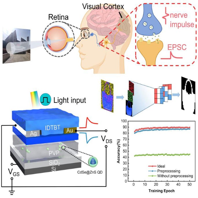
Article PDF
Download to read the full article text
Avoid common mistakes on your manuscript.
Merolla PA, Arthur JV, Alvarez-Icaza R, et al. A million spiking-neuron integrated circuit with a scalable communication network and interface. Science, 2014, 345: 668–673
Article CAS PubMed Google Scholar
Zhang X, Wu S, Yu R, et al. Programmable neuronal-synaptic transistors based on 2D MXene for a high-efficiency neuromorphic hardware network. Matter, 2022, 5: 3023–3040
Article CAS Google Scholar
Liu Y, Yang W, Yan Y, et al. Self-powered high-sensitivity sensory memory actuated by triboelectric sensory receptor for real-time neuromorphic computing. Nano Energy, 2020, 75: 104930
Guo P, Jia M, Guo D, et al. Retina-inspired in-sensor broadband image preprocessing for accurate recognition via the flexophototronic effect. Matter, 2023, 6: 537–553
Zhang Z, Wang S, Liu C, et al. All-in-one two-dimensional retinomorphic hardware device for motion detection and recognition. Nat Nanotechnol, 2022, 17: 27–32
Article PubMed Google Scholar
Li H, Jiang X, Ye W, et al. Fully photon modulated heterostructure for neuromorphic computing. Nano Energy, 2019, 65: 104000
Matthews BHC. Sensory mechanisms of the retina. Nature, 1949, 163: 423–424
Article Google Scholar
Dang B, Liu K, Wu X, et al. One-phototransistor-one-memristor array with high-linearity light-tunable weight for optic neuromorphic computing. Adv Mater, 2023, 35: 2204844
Lv Z, Chen M, Qian F, et al. Mimicking neuroplasticity in a hybrid biopolymer transistor by dual modes modulation. Adv Funct Mater, 2019, 29: 1902374
Shan L, Chen Q, Yu R, et al. A sensory memory processing system with multi-wavelength synaptic-polychromatic light emission for multimodal information recognition. Nat Commun, 2023, 14: 2648
Article CAS PubMed PubMed Central Google Scholar
Tao L, Jiang B, Ma S, et al. 3D trigonal FAPbI 3 -based multilevel resistive switching nonvolatile memory for artificial neural synapse. SmartMat, 2023, e1233
Jörntell H, Hansel C. Synaptic memories upside down: Bidirectional plasticity at cerebellar parallel fiber-purkinje cell synapses. Neuron, 2006, 52: 227–238
Zhu X, Gao C, Ren Y, et al. High-contrast bidirectional optoelectronic synapses based on 2D molecular crystal heterojunctions for motion detection. Adv Mater, 2023, 35: 2301468
Geiger M, Petrini L, Wyart M. Landscape and training regimes in deep learning. Phys Rep, 2021, 924: 1–18
LeCun Y, Bengio Y, Hinton G. Deep learning. Nature, 2015, 521: 436–444
Chen Y, Kang Y, Hao H, et al. All two-dimensional integration-type optoelectronic synapse mimicking visual attention mechanism for multi-target recognition. Adv Funct Mater, 2023, 33: 2209781
Zhang J, Guo Z, Sun T, et al. Energy-efficient organic photoelectric synaptic transistors with environment-friendly CuInSe 2 quantum dots for broadband neuromorphic computing. SmartMat, 2023, n/a: e1246
Zhu C, Liu H, Wang W, et al. Optical synaptic devices with ultra-low power consumption for neuromorphic computing. Light Sci Appl, 2022, 11: 337
Ji R, Feng G, Jiang C, et al. Fully light-modulated organic artificial synapse with the assistance of ferroelectric polarization. Adv Elect Mater, 2022, 8: 2101402
Kwon SM, Kwak JY, Song S, et al. Large-area pixelized optoelectronic neuromorphic devices with multispectral light-modulated bidirectional synaptic circuits. Adv Mater, 2021, 33: 2105017
Shan X, Zhao C, Wang X, et al. Plasmonic optoelectronic memristor enabling fully light-modulated synaptic plasticity for neuromorphic vision. Adv Sci, 2022, 9: 2104632
Wu R, Liu X, Yuan Y, et al. Biomimetic artificial tetrachromatic photoreceptors based on fully light-controlled 2D transistors. Adv Funct Mater, 2023, 33: 2305677
Hou YX, Li Y, Zhang ZC, et al. Large-scale and flexible optical synapses for neuromorphic computing and integrated visible information sensing memory processing. ACS Nano, 2021, 15: 1497–1508
Yang CM, Chen TC, Verma D, et al. Bidirectional all-optical synapses based on a 2D Bi 2 O 2 Se/graphene hybrid structure for multifunctional optoelectronics. Adv Funct Mater, 2020, 30: 2001598
Li X, Yu B, Wang B, et al. Complementary photo-synapses based on light-stimulated porphyrin-coated silicon nanowires field-effect transistors (LPSNFET). Small, 2021, 17: 2101434
Xie P, Chen X, Zeng Z, et al. Artificial visual systems with tunable photoconductivity based on organic molecule-nanowire heterojunctions. Adv Funct Mater, 2023, 33: 2209091
Zhang Q, Li E, Wang Y, et al. Ultralow-power vertical transistors for multilevel decoding modes. Adv Mater, 2023, 35: 2208600
Venkateshvaran D, Nikolka M, Sadhanala A, et al. Approaching disorder-free transport in high-mobility conjugated polymers. Nature, 2014, 515: 384–388
Liu T, Zhang X, Zhang J, et al. Interface study of ITO/ZnO and ITO/SnO 2 complex transparent conductive layers and their effect on CdTe solar cells. Int J Photoenergy, 2013, 2013: 1–8
Google Scholar
Li E, Gao C, Yu R, et al. MXene based saturation organic vertical photoelectric transistors with low subthreshold swing. Nat Commun, 2022, 13: 2898
Lillicrap TP, Santoro A, Marris L, et al. Backpropagation and the brain. Nat Rev Neurosci, 2020, 21: 335–346
Liu Y, Liu D, Gao C, et al. Self-powered high-sensitivity all-in-one vertical tribo-transistor device for multi-sensing-memory-computing. Nat Commun, 2022, 13: 7917
Abbott LF, Regehr WG. Synaptic computation. Nature, 2004, 431: 796–803
Shan L, Zeng H, Liu Y, et al. Artificial tactile sensing system with photoelectric output for high accuracy haptic texture recognition and parallel information processing. Nano Lett, 2022, 22: 7275–7283
Yu R, He L, Gao C, et al. Programmable ferroelectric bionic vision hardware with selective attention for high-precision image classification. Nat Commun, 2022, 13: 7019
Article PubMed PubMed Central Google Scholar
Qin S, Wang F, Liu Y, et al. A light-stimulated synaptic device based on graphene hybrid phototransistor. 2D Mater, 2017, 4: 035022
Wang Y, Lv Z, Chen J, et al. Photonic synapses based on inorganic perovskite quantum dots for neuromorphic computing. Adv Mater, 2018, 30: 1802883
Wang S, Chen C, Yu Z, et al. A MoS 2 /PTCDA hybrid heterojunction synapse with efficient photoelectric dual modulation and versatility. Adv Mater, 2019, 31: 1806227
Yin L, Han C, Zhang Q, et al. Synaptic silicon-nanocrystal phototransistors for neuromorphic computing. Nano Energy, 2019, 63: 103859
Park HL, Kim H, Lim D, et al. Retina-inspired carbon nitride-based photonic synapses for selective detection of UV light. Adv Mater, 2020, 32: 1906899
Zhang ZC, Li Y, Wang JJ, et al. Synthesis of wafer-scale graphdiyne/graphene heterostructure for scalable neuromorphic computing and artificial visual systems. Nano Res, 2021, 14: 4591–4600
Kim J, Song S, Kim H, et al. Light-stimulated artificial photonic synapses based on solution-processed In-Sn-Zn-O transistors for neuromorphic applications. J Alloys Compd, 2022, 903: 163873
Gupta GK, Kim IJ, Park Y, et al. Inorganic perovskite quantum dot-mediated photonic multimodal synapse. ACS Appl Mater Interfaces, 2023, 15: 18055–18064
Liang J, Yu X, Qiu J, et al. All-optically controlled artificial synapses based on light-induced adsorption and desorption for neuromorphic vision. ACS Appl Mater Interfaces, 2023, 15: 9584–9592
Mi YC, Yang CH, Shih LC, et al. All-optical-controlled excitatory and inhibitory synaptic signaling through bipolar photoresponse of an oxide-based phototransistor. Adv Opt Mater, 2023, 11: 2300089
Shao H, Li Y, Yang W, et al. A reconfigurable optoelectronic synaptic transistor with stable Zr-CsPbI 3 nanocrystals for visuomorphic computing. Adv Mater, 2023, 35: 2208497
Yan Y, Yu N, Yu Z, et al. Optoelectronic synaptic memtransistor based on 2D SnSe/MoS 2 van der Waals heterostructure under UV–ozone treatment. Small Methods, 2023, 7: 2201679
Gollisch T, Meister M. Eye smarter than scientists believed: Neural computations in circuits of the retina. Neuron, 2010, 65: 150–164
Pi L, Wang P, Liang SJ, et al. Broadband convolutional processing using band-alignment-tunable heterostructures. Nat Electron, 2022, 5: 248–254
Wang CY, Liang SJ, Wang S, et al. Gate-tunable van der Waals heterostructure for reconfigurable neural network vision sensor. Sci Adv, 2020, 6: eaba6173
Download references
Acknowledgements
This work was supported by the National Key Research and Development Program of China (2022YFB3603802), the National Natural Science Foundation of China (62374033), and Fujian Science & Technology Innovation Laboratory for Optoelectronic Information of China (2021ZZ129).
Author information
Authors and affiliations.
Institute of Optoelectronic Display, National & Local United Engineering Lab of Flat Panel Display Technology, Fuzhou University, Fuzhou, 350002, China
Changfei Liu ( 刘常飞 ), Changsong Gao ( 高昌松 ), Weilong Huang ( 黄伟龙 ), Minrui Lian ( 连敏锐 ), Chenhui Xu ( 许晨晖 ), Huipeng Chen ( 陈惠鹏 ) & Tailiang Guo ( 郭太良 )
Fujian Science & Technology Innovation Laboratory for Optoelectronic Information of China, Fuzhou, 350100, China
Joint School of National University of Singapore and Tianjin University, International Campus of Tianjin University, Binhai New City, Fuzhou, 350207, China
Changfei Liu ( 刘常飞 ), Weilong Huang ( 黄伟龙 ), Minrui Lian ( 连敏锐 ) & Wenping Hu ( 胡文平 )
Tianjin Key Laboratory of Molecular Optoelectronic Sciences, Department of Chemistry, School of Science, Tianjin University & Collaborative Innovation, Center of Chemical Science and Engineering (Tianjin), Tianjin, 300072, China
Wenping Hu ( 胡文平 )
You can also search for this author in PubMed Google Scholar
Contributions
Author contributions Chen H and Guo T conceived the project. Liu C, Gao C, and Lian M designed and performed the experiments and collected the data. Liu C, Huang W, and Xu C analyzed and discussed the data. Liu C, Chen H, and Hu W wrote the paper. All authors contributed to the general discussion.
Corresponding author
Correspondence to Huipeng Chen ( 陈惠鹏 ) .
Ethics declarations
Conflict of interest The authors declare that they have no conflict of interest.
Additional information
Supplementary information Supporting data are available in the online version of the paper.
Changfei Liu received his Bachelor’s degree from Fuzhou University in 2021. Now he is a Master student of physical electronics at the School of Physics and Information Engineering, Fuzhou University. His current research interests mainly focus on the photoelectric synaptic devices.
Supporting Information
40843_2024_2812_moesm1_esm.pdf.
Bipolar Synaptic Organic/Inorganic Heterojunction Transistor with Complementary Light Modulation and Low Power Consumption for Energy-Efficient Artificial Vision Systems
Rights and permissions
Reprints and permissions
About this article
Liu, C., Gao, C., Huang, W. et al. Bipolar synaptic organic/inorganic heterojunction transistor with complementary light modulation and low power consumption for energy-efficient artificial vision systems. Sci. China Mater. (2024). https://doi.org/10.1007/s40843-024-2812-7
Download citation
Received : 08 January 2024
Accepted : 05 February 2024
Published : 25 April 2024
DOI : https://doi.org/10.1007/s40843-024-2812-7
Share this article
Anyone you share the following link with will be able to read this content:
Sorry, a shareable link is not currently available for this article.
Provided by the Springer Nature SharedIt content-sharing initiative
- photoelectric synaptic transistor
- artificial vision system
- low energy consumption
- bipolar heterojunction transistor
- Find a journal
- Publish with us
- Track your research
Academia.edu no longer supports Internet Explorer.
To browse Academia.edu and the wider internet faster and more securely, please take a few seconds to upgrade your browser .
- We're Hiring!
- Help Center
Bipolar transistors
- Most Cited Papers
- Most Downloaded Papers
- Newest Papers
- Save to Library
- Last »
Enter the email address you signed up with and we'll email you a reset link.
- Academia.edu Publishing
- We're Hiring!
- Help Center
- Find new research papers in:
- Health Sciences
- Earth Sciences
- Cognitive Science
- Mathematics
- Computer Science
- Academia ©2024
IMAGES
VIDEO
COMMENTS
2Maine Center for Research in STEM Education, University of Maine, Orono, Maine 04469, USA (Received 1 June 2018; published 20 November 2018) The research reported in this article represents a systematic, multiyear investigation of student understanding of the behavior of bipolar junction transistor circuits using a variety of different tasks
Chapter 2: Bipolar Junction Transistor (BJT) 2.1 Introduction. It is a three la yer se miconductor device. Emitter i s highly doped and supplies the charges. Collector is moderately. doped and ...
Aiming to correct what we consider to be a deficiency, this paper wishes both to present some intuitive explanations on the functional features of the Bipolar Junction Transistor and to emphasize ...
Advanced Functional Materials, part of the prestigious Advanced portfolio and a top-tier materials science journal, publishes outstanding research across the field. Abstract Bipolar junction transistors (BJTs), the basic building blocks of integrated circuits, are deployed to control switching applications and logic operations.
Bipolar junction transistors (BJTs) are a major class of transistors with their own nomenclature: The input, output, and control terminals are denoted emitter, collector, and base, respectively.A pnp-BJT can bee seen as two pn-junctions sharing a narrow base region, where the emitter and collector are p-doped and the base is n-doped.Anion- and cation-selective membranes are the ionic ...
In this paper, a BJT EMC model that satisfies both functionality and EMC analysis requirements was established based on physical characteristic measurement. First, comprehensive and systematic methods for measurement and extracting SPICE parameters based on physical BJTs are presented, including a proposed curve-fitting calculation method for ...
This paper summarizes the results of investigations of bipolar transistors made in VESTIC (Vertical Slit Transistor-based Integrated Circuits) technology. This technology was proposed by W. Maly as an alternative to classical bulk CMOS technology. However, the basic VESTIC cell can be used not only to make field effect transistors but also to make bipolar transistors. Their structures differ ...
In this paper, we propose the concept of a ballistic lateral heterojunction bipolar transistor based on transition metal dichalcogenides (TMDCs), and assess its potential in elec-tronics applications with self-consistent quantum transport and electrostatics simulations using the nonequilibrium Green's function (NEGF) formalism [13,14].
<P>The bipolar junction transistor (BJT), the first practical solid-state amplifying device, represents one of the watershed achievements in human history. Transistors are essential to electronics and hence modern life. They have achieved this notoriety because they possess two fundamental capabilities: 1) to function as an amplifier of time-varying voltage or current signals, and 2) to ...
How N and P type semiconductors are placed in the transistor 2. TRANSISTOR (BJT) A typical transistor (BJT) consists of three PNP and NPN halves. The arrangement of semiconductor crystals is as ...
This explanatory research paper examines and discusses the working principles behind the bipolar junction transistor and its specific application as a switch. II. Bipolar Junction Transistor as a Switch A Historical Overview of Transistors The invention of transistors has revolutionized the modern world because it was primary instrumental
In the previous research, we investigated a p-n junction with an abrupt doping profile made of a graphone sheet . Evidently, a pair of similar 2D junctions may provide a fairly good basis for operation of 2D bipolar junction transistors (2D-BJTs). ... In this paper, we revisit the design of a 2D-BJT with abrupt doping profile, and graphone is ...
Organic field-effect transistors (FET) were first reported in 1986 and have shown impressive improvements in the past two decades 4,5,6,7,8,9,10,11.Nevertheless, they are still restricted to the ...
The properties of the bipolar junction transistor derive from those of the PN junction, as it essentially consists of two junctions: base-emitter and base-collector. The fairly strong reverse polarization of the base-collector junction may allow carriers to acquire a sufficiently high energy to cause the impact ionization phenomenon. The ...
These HLE bipolar transistors also display a smaller percentage increase in maxi- mum dc current gain over temperature than that of conventional bipolar transistors. Thus stable high-gain bipolar power transistors were realized with a high-low emitter junction and a uniform lightly-doped base region. 5.
1.1. A Brief Background on Bipolar Junction Transistor. The BJT is an electronic device that is part of the most varied types of electronic equipment both in discrete form and the well-known integrated circuit (IC) form [].The bipolar transistors are also part of several types of industrial controllers, electronic systems for vehicles, airplanes, ships, linear accelerators, scientific ...
Photoelectric synaptic transistors integrate optical sensing and synaptic functions into a single device, which has significant advantages in neuromorphic computing for visual information, recognition, memory, and processing. However, the weight updating of existing photoelectric synapses is predominantly based on separate utilization of light and electrical stimuli to regulate synaptic ...
1. Introduction. The insulated gate bipolar transistor (IGBT) plays an essential role in the new energy industry [1], with its impressive high-power switching capabilities and efficient conversion abilities, providing efficient and reliable energy conversion and management for new energy devices [2].Especially with the continuous growth in demand for electric vehicles and charging stations ...
Construction The invention of transistor by Barden, Brattain and Shockley in 1948 has started the real electronic era. The bipolar transistor consists of a semiconductor crystal in which a very thin n-type (p-type) layer is sandwiched by two p-type (n-type) layers, as shown schematically in Fig. 1.
In this paper, we limit our discussion to a total of five research tasks, which focus on different aspects of transistor circuit behavior. A sixth related task targeting the. behavior of ac biasing networks (which are frequently included in transistor circuits) has been. detailed in a separate publication [33].
DOI: 10.1016/j.ijthermalsci.2019.106106 Corpus ID: 204204847; Effects on thermal performance enhancement of pin-fin structures for insulated gate bipolar transistor (IGBT) cooling in high voltage heater system
In this paper, we present a high speed junction field-effect-transistor (JFET) operational amplifier (OPA). It adopts N-channel JFET (N-JFET) differential input stage, full complementary differential gain stage and common-emitter output stage. It is fabricated on an especial complementary bipolar process compatible with N-JFET module.
A magnetic bipolar transistor is a bipolar junction transistor with one or more magnetic regions, and/or with an externally injected nonequilibrium (source) spin. It is shown that electrical spin injection through the transistor is possible in the forward active regime. It is predicted that the current amplification of the transistor can be tuned by spin.
Recently Schottky diodes are offered by both USA and Europe based companies. Active switching devices such as bipolar junction transistors (BJTs), field effect transistors (JFETs and MOSFETs) are now available on the commercial market. The interest is rapidly growing for these devices in high power and high temperature applications.