

Create Professional Science Figures in Minutes
Join the largest science communication research community.

THOUSANDS OF ICONS
Browse over 50,000 icons and templates from over 30 fields of life science, curated and vetted by industry professionals.
DRAG AND DROP
Simple drag-and-drop functionality enables you to create scientific figures up to 50 times faster.

CUSTOM ICONS
Find icons you need for even the most specialized fields of life science, or we’ll create it in as little as 48 hours ( conditions apply ).

Figure: During HSV infection, memory CD4-T-cells respond to antigens in neural tissue by secreting IFN-γ and loosening tight junctions between endothelial cells, allowing antibodies to cross the blood-brain-barrier.

Ready to get started?
Get in touch
555-555-5555

Limited time offer: 20% off all templates ➞

Guide to Using Science Images for Research Papers
One easy way to include science images in your manuscripts is to download and customize them for your figures..
When downloading images from the internet to use in your scientific papers and presentations, you need to be careful that they match the copyright, resolution, and sizing rules that allow them to be used in academic journals. This science image guide provides tips to help you choose the right kinds of files that you can use to create your own impressive designs.

Which image format is best for research papers?
There are two categories of images that can be used for scientific publications: editable and uneditable. Editable images that can be fully customized and scaled without losing resolution are called vector files. Uneditable images don't allow you to adjust the design or color and come in wide range of formats from low to high resolution. Both of these image types can be used in scientific papers as long as you follow the proper copyright and resolution rules. Learn more about these image types and the different uses below.
1. Editable Images
The best kind of science images are editable vector files that allow you to customize the designs to best match the main points of your research. These include image file types such as Scalable Vector Graphics (.svg), Adobe Illustrator (.ai), Affinity Designer (.afdesign), Encapsulated PostScript (.eps), and some files in PowerPoint (.pptx) if they were drawn using PowerPoint shape tools.
Editable Image Tips:
- Editable images are important because some scientific journals, such as Science, require that you provide them with figures that are formatted using editable vector files.
- Be cautious of using images and database tools that only offer limited design customization options such as BioRender. Partially editable images can be difficult to make an illustration that looks professional and seamless with your data and other designs.
- Vector images have customizable sizes, resolution and transparent backgrounds, so you can always scale the image and insert it into any background.
- Make sure you follow the copyright rules associated with your image download. Some vector image databases require attribution and others allow you to use them for any purpose.

How to Find Editable Images
The easiest ways to find editable images is to explore science image databases or use Google search. I recommend using the search terms "drawings", "vector art", or "vector images" paired with the image type keyword.
The example below shows the Google Image search results for "cancer cell drawings" with a variety of different options for downloading different types of science images. You will still need to make sure that the image is available as a vector file type to be fully editable (e.g. SVG, AI, or EPS file types). Most vector images will require some sort of payment or subscription to download the high resolution files and use without copyright issues.

1. Uneditable Images
The second best format is uneditable images. Common uneditable image types are PNG, TIFF, or JPEG formats and these can be incorporated into your scientific figures and presentations as long as they have high enough resolution and have copyright rules that allow you to use them in academic publications.
Uneditable image tips:
- Check the resolution of downloaded images to make sure they are high enough to use in scientific publications without looking grainy or unclear (see the "How to check image resolution" instructions in the section below).
- Try to find PNG images with transparent backgrounds to make it easier to incorporate into your scientific figures and posters.
- Be very careful in checking the source of uneditable images and follow all copyright rules associated with the image. Uneditable image are more likely to have copyright rules associated with them that do not allow their use in scientific journals.

How to Find High Resolution and Transparent Images
The easiest ways to find high resolution and transparent images is to explore science image databases or use Google search. I recommend using the search terms "transparent background" and using the Google "Tools" feature to limit the search for "Large" images.
The examples below shows the Google Large Image search results for "plant cell diagram transparent background" that show a variety of different options for downloading high resolution and transparent science images.

What image sizes are best for scientific publication?
Size and resolution are important because images need to be high resolution enough to show sharp shapes and lines when it is used in a printed or digital figure. Below are tips on how to choose the right image sizes and resolutions.
Image Resolution
Resolution is the most important aspect of a downloaded image or scientific figure and affects the sharpness of the details. A low-resolution image will have around 72 PPI and high resolution images are at least 300 PPI.
- Most scientific journals require images and figures to be at least 300 PPI/DPI.
- The "PPI" stands for Pixels Per Inch and is used when referring to digital file resolution and "DPI" stands for Dots Per Inch and is used for printing resolution.

How to Check Image Resolution:
- Windows computer: Right-click on the file, select Properties, then Details, and you will see the DPI in the Image section, labeled Horizontal Resolution and Vertical Resolution.
- Mac computer: Open the image in Preview and select Tools, then Adjust Size, and find the label Resolution.
The size requirements will depend on how you plan to use the image. Most scientific journals use a maximum figure width of 180mm, so if you only plan to use images in scientific publications, then you only need them large enough to look sharp within a 180 mm wide figure (~600 pixels wide).
If you plan to use the image in presentation or posters slides, you will need to have much larger images to not have resolution issues when shown on a big screen that is 1280 x 720 pixels or printed on a poster that is approximately 48 x 36 inches.
How Can I Find Copyright-Free Images?
Copyright laws ensure that an image is only used in a way that is approved by the image creator. The best way to ensure that you download images with copyright rules that allow you to use them for academic journal submissions is to read the fine print on the image source. The summary below describes how to find images that are allowed for use in scientific papers.
Copyright License Review
Anyone who creates their own original artwork has the right to be acknowledged as the creator of that image. They automatically own the copyright for the image, which means that legally, they have the right to decide where and how that image can be used. In order to be able to use images in scientific papers, you will need to know what kind of copyright license is being used, which you can usually find by looking for the original source of the image or by reading the fine print of the image database.
Types of copyright licenses for scientific use:
- Public Domain - Images generally become public domain after 70 years after the creator's death. If the copyright is not renewed on the creator's behalf, the image can become part of the ‘public domain’, and the copyright no longer applies.
- Creative Commons 4 - You can adapt and share the image in anyway you like, but this license requires attribution, so you will need to include the original creator in the acknowledgements of the research paper, posters, and acknowledged on your presentation slides.
- Stock Images - Image databases that allow you to license the designs. Make sure to read the fine print on how you are allowed to use the image (e.g. personal and commercial uses).

How to Find Copyright-Free Images:
Look for image databases that have copyright licenses that allow you to use the images "For personal, academic, and commercial projects and to modify it" such as:
- FreePik
- Simplified Science
- Wikimedia Commons
NOTE: Some copyright-free image databases may still require that you attribute the illustration to the original author in your scientific publication. Read the fine print to make sure you are using the image correctly!
Here is an example of Simplified Science Usage Rules for comparison to other image databases.
How to Use Downloaded Images in Publications?
After downloading images, the next step is to format them into your scientific designs. Two of the most common software tools that scientists use for figure formatting are Adobe Illustrator and PowerPoint. Below is a link to free online courses that show you how to use the downloaded images in your scientific publications and graphical abstracts.
Create professional science figures with illustration services or use the online courses and templates to quickly learn how to make your own designs.
Interested in free design templates and training.
Explore scientific illustration templates and courses by creating a Simplified Science Publishing Log In. Whether you are new to data visualization design or have some experience, these resources will improve your ability to use both basic and advanced design tools.
Interested in reading more articles on scientific design? Learn more below:

Scientific Presentation Guide: How to Create an Engaging Research Talk

Data Storytelling Techniques: How to Tell a Great Data Story in 4 Steps

Best Science PowerPoint Templates and Slide Design Examples
Content is protected by Copyright license. Website visitors are welcome to share images and articles, however they must include the Simplified Science Publishing URL source link when shared. Thank you!
Online Courses
Stay up-to-date for new simplified science courses, subscribe to our newsletter.
Thank you for signing up!
You have been added to the emailing list and will only recieve updates when there are new courses or templates added to the website.
We use cookies on this site to enhance your user experience and we do not sell data. By using this website, you are giving your consent for us to set cookies: View Privacy Policy
Simplified Science Publishing, LLC
How to Create Publication-Quality Figures A step-by-step guide (using free software!) Benjamin Nanes
Introduction, data don't lie, follow the formatting rules, transparency, a computer's view of the journal page, raster data vs. vector data, rasterization and resampling, color spaces, hsl, hsv, and hsb, yuv, ycbcr, and ypbpr, indexed, mapped, and named colors, preparing figure components, graphs and charts, exporting vector graphics from r, exporting vector-format charts from any other program, high-bit-depth images, lookup tables, setting the lut range, comparison to photo editing programs, multi-channel images, generating the 8-bit rgb image, ordinary images, figure layout, importing vector files, importing images, clipping masks, calculating scale bars, exporting final figure files, image compression, creating tiff images, creating eps or pdf files, the bottom line, cmyk figures, preparing raster figure components for cmyk, color conversion, author information.
So, after months (years?) of toil in the lab, you're finally ready to share your ground-breaking discovery with the world. You've collected enough data to impress even the harshest reviewers. You've tied it all together in a story so brilliant, it's sure to be one of the most cited papers of all time.
Congratulations!
But before you can submit your magnum opus to Your Favorite Journal , you have one more hurdle to cross. You have to build the figures. And they have to be "publication-quality." Those PowerPoint slides you've been showing at lab meetings? Not going to cut it.
So, what exactly do you need to do for "publication-quality" figures? The journal probably has a long and incomprehensible set of rules. They may suggest software called Photoshop or Illustrator. You may have heard of them. You may be terrified by their price tags.
But here's the good news: It is entirely possible to build publication-quality figures that will satisfy the requirements of most (if not all) journals using only software that is free and open source. This guide describes how to do it. Not only will you save money on software licenses, you'll also be able to set up a workflow that is transparent, maintains the integrity of your data, and is guaranteed to wring every possible picogram of image quality out of the journal's publication format.
Here are the software packages that will make up the core of the figure-building workflow:
R — Charts, graphs, and statistics. A steep learning curve, but absolutely worth the effort. If you're lazy though, the graph-making program that you already use is probably fine.
ImageJ — Prepare your images. Yes, the user interface is a but rough, but this is a much more appropriate tool than Photoshop. For ImageJ bundled with a large collection of useful analysis tools, try the Fiji distribution .
Inkscape — Arrange, crop, and annotate your images; bring in graphs and charts; draw diagrams; and export the final figure in whatever format the journal wants. Illustrator is the non-free alternative. Trying to do this with Photoshop is begging for trouble.
Embed and Crop Images extension for Inkscape and The PDF Shrinker — Control image compression in your final figure files.
The focus on free software is facultative rather than ideological. All of these programs are available for Windows, Mac, and Linux, which is not always the case for commercial software. Furthermore, the fact that they are non-commercial avoids both monetary and bureaucratic hassles, so you can build your figures with the same computer you use to store and analyze your data, rather than relying on shared workstations (keep backups!) . Most importantly, these tools are often better than their commercial alternatives for building figures.
First of all, this guide is not intended to be a commentary on figure design. It's an introduction to the technical issues involved in turning your experimental data into something that can be displayed on a computer monitor, smart-phone, or dead tree while preserving as much information as possible. You will still be able to produce ugly and uninformative figures, even if they are technically perfect.
So, before we dive into the details of the figure-building workflow, let's take a moment to consider what we want to accomplish. Generally speaking, we have four goals: accurately present the data, conform to the journal's formatting requirements, preserve image quality, and maintain transparency.
And neither should your figures, even unintentionally. So it's important that you understand every step that stands between your raw data and the final figure. One way to think of this is that your data undergoes a series of transformations to get from what you measure to what ends up in the journal. For example, you might start with a set of mouse weight measurements. These numbers get 'transformed' into the figure as the vertical position of points on a chart, arranged in such a way that 500g is twice as far from the chart baseline as 250g. Or, a raw immunofluorescence image (a grid of photon counts) gets transformed by the application of a lookup table into a grayscale image. Either way, exactly what each transformation entails should be clear and reproducible. Nothing in the workflow should be a magic "black box."
Following one set of formatting rules shouldn't be too hard, at least when the journal is clear about what it expects, which isn't always the case. But the trick is developing a workflow that is sufficiently flexible to handle a wide variety of formatting rules — 300dpi or 600dpi, Tiff or PostScript, margins or no margins. The general approach should be to push decisions affecting the final figure format as far back in the workflow as possible so that switching does not require rebuilding the entire figure from scratch.
Unfortunately, making sure your figures look just the way you like is one of the most difficult goals of the figure-building process. Why? Because what you give the journal is not the same thing that will end up on the website or in the PDF. Or in print, but who reads print journals these days? The final figure files you hand over to the editor will be further processed — generally through some of those magic "black boxes." Though you can't control journal-induced figure quality loss, you can make sure the files you give them are as high-quality as possible going in.
If Reviewer #3 — or some guy in a bad mood who reads your paper five years after it gets published — doesn't like what he sees, you are going to have to prove that you prepared the figure appropriately. That means the figure-building workflow must be transparent. Every intermediate step from the raw data to the final figure should be saved, and it must be clear how each step is linked. Another reason to avoid black boxes.
This workflow should accomplish each of these goals. That being said, it's not really a matter of follow-the-checklist and get perfect figures. Rather, it's about understanding exactly what you're doing to get your data from its raw form to the (electronic) journal page.
In order to understand how to get data into a presentable form, we need to consider a few details of how visual information gets represented on a computer.
There are two fundamentally different ways that visual information can be described digitally. The first is by dividing an image into a grid, and representing the color of each cell in the grid — called a pixel — with a numeric value. This is raster data , and you're probably already familiar with it. Nearly all digital pictures, from artsy landscapes captured with high-end cameras to snapshots taken by cell phones, are represented as raster data. Raster data is also called bitmap data.
The second way computers can represent images is with a set of instructions. Kind of like "draw a thin dashed red line from point A to point B, then draw a blue circle with radius r centered at point C," but with more computer-readable syntax. This is called vector data, and it's usually used for images that can be decomposed into simple lines, curves, and shapes. For example, the text you're reading right now is represented as a set of curves .
Storing visual information as raster or vector data has an important impact on how that image gets displayed at different sizes. Raster data is resolution dependent . Because there are a finite number of pixels in the image, displaying the image at a particular size results in an image with a particular resolution, usually described as dots per inch (dpi) or pixels per inch (ppi). If a raster image is displayed at too large a size for the number of pixels it contains, the resolution will be too low, and the individual pixels will be easily visible, giving the image a blocky or "pixelated" appearance.
In contrast, vector data is resolution independent . Vector images can be enlarged to any size without appearing pixelated. This is because the drawing instructions that make up the vector image do not depend on the final image size. Given the vector image instruction to draw a curve between two points, the computer will calculate as many intermediate points as are necessary for the curve to appear smooth. In a raster image a curve must be divided into pixels when the image is created, and it isn't easy to add more pixels if the image is enlarged later.
Often, raster images have a specified resolution stored separately from the pixel values (a.k.a. metadata ). This resolution metadata isn't really an integral part of the raster image, though it can be useful for conveying important information, such as the scale factor of a microscope or the physical size at which an image is intended to be printed. Similarly, vector images may use a physical coordinate system, such as inches or centimeters. However, the coordinates can be scaled by multiplication with a constant, so, as with raster images, the image data is independent of the physical units.
So, if vector data is resolution independent, why use raster data at all? It's often a question of efficiency. Vector data is great for visual data that can be broken down into simple shapes and patterns. For something like a graph or a simple line drawing, a vector-based representation is probably going to be higher quality and smaller (in terms of file size) than a raster image. However, as images get more complex, the vector representation becomes progressively less efficient. Think of it this way: As you add more shapes to an image, the number of drawing instructions needed for the vector representation also increases, while the number of pixels in the corresponding raster image can stay the same. At some point, resolution independence is no longer worth the cost in file size and processing time.
There's a second very important reason why raster data may be preferable to vector data. Many images are so complex that the simplest shapes into which they can be divided are, effectively, pixels. Consider a photograph. One could create a vector image based on outlines or simple shapes in the picture, but this would be a cartoon approximation — shading and textural details would be lost. The only way to create a vector image capturing all the data in the photograph is to create many small shapes to represent the smallest details present — pixels.
Another way to think about this is that some visual data is natively raster. In raster images from digital cameras, each pixel corresponds to the signal captured by a single photosite on the detector. (This is literally true for the camera attached to your microscope, but the full story is a bit more complicated for consumer cameras.) The camera output is pixels, not lines and curves, so it makes sense to represent the image with raster, rather than vector data.
At some point, almost all vector data gets converted into raster data through a process called rasterization . Usually this happens just before the image is sent to a display or printer, because these devices are built to display and print pixels. That's why your monitor has a screen resolution, which specifies the pixel dimensions of the display area. Because vector-format images are resolution independent, they can be rasterized onto pixel grids of any size, but once rasterized, the image is then tied to that particular pixel grid. In other words, the rasterized image contains less information than the original vector image — rasterization causes a loss of image quality.
A similar loss of image information can occur when raster images are redrawn onto a new pixel grid. This process, called resampling , almost always results in an image that is lower quality, even if the pixel dimensions of the resampled image are increased. Why? Consider an image that is originally 100px × 100px, but is resampled to 150px × 150px. The problem is that many of the pixels in the new image do not directly correspond to pixels in the old image — they lie somewhere between the locations of the old pixels. We could assign them values based on the average of the neighboring pixels, but this will tend to blur sharp edges. Alternatively, we could just duplicate some of the old pixels, but this will shift boundaries and change shapes. There are fancier algorithms too, but the point is, there is no way to exactly represent the original raster data on the new pixel grid.
The takeaway from all this is that rasterization and resampling are to be avoided whenever possible . And when, as is often the case, rasterization and resampling are required to produce an image with a particular size and resolution, rasterization and resampling should only be done once — and as the very last steps in the workflow. Once vector information has been rasterized and raster images have been resampled, any further manipulation risks unnecessary quality loss.

Whether an image is represented by raster or vector data, there are a variety of ways to store color information. Every unit of the image — pixels in raster images and shapes/lines/curves in vector images — has an associated color value. There isn't any practical way to represent the more or less infinite light wavelengths (and combinations thereof) perceived as different colors in the real world, so in the digital world, we take shortcuts. These shortcuts mean that only a finite, though generally large, number of colors are available. Different shortcuts make available slightly different sets of colors, called color spaces .
More precisely, color spaces are sets of colors, while the types of numerical color descriptions discussed below are color models . Color models are mapped onto color spaces, ideally based on widely agreed upon standards so that a particular color model value actually appears the same in all situations. Of course things are generally more complicated than that. Rarely do different computer monitors, for example, display colors exactly the same way.
The simplest color representation has no color at all, just black, white, and shades of gray. A grayscale color is just a single number. Usually, lower numbers are closer to black and higher numbers are closer to white. The range of possible numbers (shades) is determined by the bit depth , discussed later. Another name for this color model is single-channel , which comes from raster images, where each pixel stores one number per image channel .
Adding actual color means adding more numbers (a.k.a., more channels). The most common system uses three channels, and is named after the colors each of them represents: red , green , and blue . RGB is an additive color model — the desired color is created by adding together different amounts of red, green, and blue light. Red and green make yellow; red and blue make purple; green and blue make aqua; and all three together make white. Computers use RGB color almost exclusively. It's also the color model journals want to see in your final figures, the better for displaying them on readers' digital devices. This workflow builds figures using RGB color.
Another way to add color to an image is to subtract it. In subtractive color models , each channel represents a pigment absorbing a certain color. CMYK color represents a common color printing process, with cyan , magenta , yellow , and black inks (the K stands for "key"). Once upon a time, journals would ask for CMYK figures to facilitate printing, but now, when there is a print edition, the journal's production department usually handles the conversion from RGB to CMYK. If, for some reason, Your Favorite Journal insists on CMYK figures, you'll need to take a look at the appendix, which discusses some possible solutions (none very good, unfortunately). Note that since CMYK color has four channels, a CMYK raster image will be 1/3 larger than the equivalent RGB raster image. The CMYK color space also contains 1/3 more possible unique colors than the RGB color space, although in practice, RGB models usually represent a broader range of perceived colors than CMYK models.
Several related models specify colors not by adding or subtracting primary colors, but with parameters related to color perception. These generally include hue (sort of like wavelength), saturation (the precise definition varies, but some measure of color intensity), and lightness , value , or brightness (different kinds of dark/light scales). You're most likely to encounter one of these models in a color-picker dialog box, since the maps of these spaces tend to be more intuitive than RGB or CMYK. However, the colors are usually mapped directly to an RGB model.
Similar to the HSL family of color models, these models include separate brightness and hue components. The Y channel is called the luminance value, and it is basically the grayscale version of the color. The other two channels are chrominance values, different systems for specifying hue. These color models are associated with old-fashioned analog video (think pre-2009 television) and various video compression formats where some color information is discarded to reduce the video size (loss of chrominance information is less noticeable than loss of luminance information).
If an image contains relatively few colors, it's sometimes possible to save space by indexing them in a color table . Each color in the table can then be identified with a single index value or label, such as "SaddleBrown" , which your browser probably maps to RGB (139,69,19) . Spot colors are named colors used to refer to specific inks for printing rather than for subsetting the RGB color space.
The range of numbers available in a particular channel is determined by the channel's bit depth , named for the number of bits (0s and 1s) used to store each value. Images with higher bit depth can describe finer shades and colors, though at the cost of increased file size. Pixels of a 1-bit single-channel raster image can hold one of two values, 0 or 1, so the image is only black and white. Pixels of an 8-bit image hold values from 0 to 255, so the image can include black, white, and 254 shades of gray in between. Pixels of a 16-bit image hold values from 0 to 65,535. However, the 8-bit image will be eight-times the file size of the 1-bit image, and the 16-bit image will be twice the file size of the 8-bit image, assuming they all have the same pixel dimensions.
Nearly all computer monitors are built to display 3-channel 8-bit images using the RGB color model. That's (2 8 ) 3 ~ 16.77 million possible colors and shades, if you're counting. 8-bit RGB is so deeply ingrained in computer graphics, that you're relatively unlikely to encounter anything else in ordinary computer use, with the exception of 8-bit grayscale or an 8-bit single-channel color table mapped to 8-bit RGB values. 8-bit RGB is sometimes called 24-bit RGB, because 8-bits per channel × 3 channels = 24-bits total per pixel.
When a larger than 8-bit image does get produced — even the sensors in most cheap digital cameras capture images that are 10-bits per channel — it is often automatically down-sampled to 8-bit. This is fine for ordinary photos, but potentially problematic for microscopy images. That fancy camera attached to your microscope probably captures 12- to 16-bit images. One of the major challenges of building figures with these images is creating the necessary 8-bit representations of them without inadvertently hiding important information. Information will inevitably be lost, but it's important that the transformation to 8-bit is fully under your control.
You'll often see 8-bit RGB values in base-16 or hexadecimal notation for compactness. This is usually a string of 6 digits/letters, often preceded by "#" or "0x", with each character pair representing one channel. The letters "a" through "f" are used to represent "digits" 10 through 15. For example "6c" equals (16×6)+12 = 108 in base-10. " #ff9933 " is RGB (255,153,51) .
Now that we've covered the basics of how computers represent visual information, let's move on to the nuts and bolts of building a figure. We'll consider a three-step workflow: preparing individual figure components from your data, combining multiple components together in a figure, and exporting the final figure file in Your Favorite Journal 's preferred format.
Graphs and charts are obvious candidates for vector data. They're easily decomposed into shapes ( bar -chart, dot -plot), and if you have to resize them, you want all those lines and curves to stay sharp and un-pixelated. Even if you will need to submit your final figures as raster images, it makes sense to keep charts as vector drawings as long as possible to avoid quality loss from resampling.
Lots of software packages can be used to draw charts and export them as vector data, but my personal favorite is R . R is a scripting language focused on statistical computations and graphics. It's free, open-source, and has a large variety of add-on packages, including the Bioconductor packages for bioinformatics. Plus, because R is a scripting language, it's easy to customize charts, keep a complete record of how you made them, and automate otherwise repetitive tasks. I even used several R scripts to help build this website, although that's not one of its more common uses.
The downside of R's power and flexibility is a substantial helping of complexity. If you're on a deadline, you might want to skip down to the part about saving vector-format charts from other programs . Know too that the steepness of the learning curve is inversely proportional to your programming experience. That said, the ultimate payoff is well worth the initial effort. There are lots of books and websites about R — UCLA has a very nice introduction — so here we'll restrict our focus to how to take a chart you've created in R and export it in a format that can be placed into your final figures.
This section assumes a basic familiarity with R. If you want to put off learning R until later, skip down to the next section .
In R, objects called devices mediate the translation of graphical commands. Different devices are used to create on-screen displays, vector image files, and raster image files. In an R console, type ?Devices to see a list of what's available. If you don't explicitly start a device, R will start one automatically when it receives a graphics command. The default device is operating system-dependent, but it is usually an on-screen display.
The easiest device to use for exporting charts in vector format is pdf , which, as you might guess, makes PDF files. Other vector-format devices are also possible, including postscript , cairo_ps , svg , cairo_pdf , and win.metafile . They all have their strengths and weaknesses, but I've found that pdf reliably produces PDFs that are both consistently viewable on many computers and easily imported into Inkscape for layout of the final figure.
All you need to do to get PDF files of your figures is to wrap your plotting code in commands to open and close a pdf device:
And that's it. There are just a few bits to keep in mind:
Setting useDingbats = FALSE on the pdf device makes larger files, but it also prevents issues when importing some charts into Inkscape.
By default, pdf measures fonts in points (1/72 in.), but everything else in 1/96 in.
The default color space is RGB. It's possible to create a CMYK-formatted PDF, but the conversion process is not well documented.
The default page size is 7 in. × 7 in. If you need to change this, set width = X, height = Y when you open the device.
If you want to try out a different device, just replace pdf with your device of choice. Keep in mind that some devices produce raster images instead of vector images.
Don't forget to call dev.off() to close the device, or you won't be able to open your PDF.
Not all chart-making programs give you an explicit option to export charts as vector-format files such as PDF, PostScript, or EPS. If one of those options is available, use it (of the three, PDF is usually the best choice for importing into Inkscape for layout of the final figures). If not, printing the chart and setting a PDF maker as the printer will often do the trick. Don't worry if there's more on the page than just your chart, since it will be possible to pull out the chart by itself when you import it into Inkscape. To check if the resulting PDF really does contain vector data (PDFs can also contain raster images), open the file and zoom in as much as you can. If you don't see any pixels, you're all set. This method works for charts created in Excel or PowerPoint — just save the whole spreadsheet or presentation as a PDF.
Most measurement tools that produce raster data — from cameras used for immunofluorescence microscopy to X-ray detectors — don't produce images that are directly displayable on a computer screen. They produce high-bit-depth images, and including these images in figures often presents a challenge. On the one hand, the images are natively composed of raster data, so the actual pixel values have important meaning which we want to preserve. However, because they are not directly displayable, they must be downsampled before they can be included in a figure. Our goal is to transform high-resolution, high-bit-depth images to 8-bit RGB in a way that is reproducible and does not hide important information from the original data.
The process of preparing a raster image for display in a figure should be kept completely separate from image analysis and quantification, which should always be based on the original, unaltered image data . Figure preparation should also be kept separate from and downstream of processing steps intended to apply to actual measurements, such as deconvolution algorithms. It is important to save original image data along with a record of every transformation applied to derive the image displayed in a figure.
The most useful program for preparing high-bit-depth images for publication is ImageJ . It can open a very large variety of original high-bit-depth image formats which is both convenient and important for maintaining the integrity of your data. It also has useful analysis tools (many contained in the Fiji distribution), is open-source and easy to extend, and gives you complete control of the transformation to an 8-bit RGB image. While many popular photo editing programs, including Photoshop, can be used to open high-bit-depth images and convert them to 8-bit RGB, none offer the transparency and degree of control provided by ImageJ. That flexibility is important, both for preparing the highest quality presentation of your data and for ensuring that important information from your data is not inadvertently hidden.
The key to creating a figure-ready image from high-bit-depth raster data is a lookup table, or LUT for short. The LUT is a function mapping each potential value in the high-bit-depth image to a corresponding 8-bit RGB value. Suppose, for example, you have a 12-bit image, which can contain pixel values from 0 to 4,095. One LUT might map 0 to RGB (0,0,0) , 4,095 to RGB (255,255,255) , and every value in between 0 and 4,095 to the linearly interpolated RGB value between black and white. This LUT would produce a simple grayscale image. However, it's not the only possible LUT. Another LUT might map values from the 0-1,000 range specifically to the red channel – RGB (0,0,0) to RGB (255,0,0) – and values from the 1,001-4,095 range to grayscale values. The advantage of a LUT such as this is that it increases the ability to discriminate between original data values in the final figure. After all, there is no way to map 4,095 shades of gray onto 255 shades of gray without loosing some detail.
It's worth noting that whenever a high-bit-depth image is displayed on a computer monitor, there is an implicit LUT which automatically generates an 8-bit RGB image. This is because both monitors and the software controlling them are built to display 8-bit RGB values — they don't know what to do with raster data using other bit depths or color models. ImageJ is such a useful program because it deals with the LUT explicitly.
To try out different LUTs in ImageJ, open up an image – stick with a single-channel image for now – and click on the LUT button in the toolbar (alternatively, choose Image > Lookup Tables from the menu). This will show a rather large list ranging from grayscale to primary colors to plenty of more fanciful options. Just stay away from the Apply LUT button, which has the totally unhelpful function of downsampling the image to single-channel 8-bit, rather than what we want to eventually get to, 8-bit RGB. For now, just pick a LUT you like.

If for some reason you're not happy with the available choices, it is possible to create a custom LUT ( Image > Color > Edit LUT... ). Note that LUTs in ImageJ are limited to 256 possible values, with everything else determined by interpolation.
Once you've decided on a LUT, the next step is to determine the range of values on which you want it applied. It will often be the case that the interesting information in your high-bit-depth raster data is concentrated in the middle of range — in other words, very few pixels have values that are very close to zero or very close to the maximum value. Remember that it usually isn't possible to assign a unique color for every value, so when this is the case, it makes sense to focus your attention on the range containing most of the pixels.
To set the LUT range in ImageJ, you can use either of two tools: Image > Adjust > Brightness/Contrast... ( Shift-C ) or Image > Adjust > Window/Level... . The Brightness/Contrast tool lets you set the minimum and maximum pixel values which will be mapped to the extremes of the LUT. Pixels between the minimum and maximum values are assigned RGB values based on the LUT. Any pixels below the minimum or above the maximum don't disappear, but they are forced to the LUT extremes, and won't be distinguishable from each other.
The Brightness/Contrast tool also lets you set properties called "brightness" and "contrast," which are just parameters used to set the minimum and maximum pixel values indirectly. Adjusting the brightness shifts the minimum and maximum together, while adjusting contrast brings the minimum and maximum closer together or farther apart. The Window/Level tool does exactly the same thing — window is the equivalent of contrast, and level is the equivalent of brightness.
Both tools conveniently display a histogram of your image, which is a good quick check to make sure you're not hiding too much of your data below the minimum or above the maximum (to see a larger histogram, click on your image and press H ). Also with both tools, if you want to set values by typing them in rather than with sliders, click on the Set button. Avoid the Apply button, which will downsample your image and prevent further changes.
If you're familiar with photo editing programs, all of this might sound a bit familiar. These programs also let you adjust brightness and contrast, and they do accomplish more or less the same thing. The main difference is that in most photo editing programs, these commands actually transform the underlying image data. In ImageJ, they just alter the mapping function for the LUT, and no actual changes are made to the raster data until you create an 8-bit RGB image. That means that in photo editing programs, adjusting the brightness and contrast causes the loss of image information — i.e. a reduction in image quality. This loss of information will occur during the creation of the RGB image in ImageJ too, but in photo editing programs, each adjustment results in the loss of more information. Unless you are extremely disciplined and make only one adjustment, the quality of the final image will suffer. Since changing the LUT in ImageJ does not affect the original raster data, it's much easier to preserve image quality, even if you want to test out lots of different LUT settings.
Some photo editing programs also allow you to make other adjustments affecting images, such as gamma corrections or curves to transform color values. These adjustments basically just define implicit LUTs — if the input value is plotted on one axis and the output value is plotted on the other, the LUT can be visualized as a line or curve defining how the different input values are mapped to outputs. Gamma is just a way to specify a simple curve, but in principle, all sorts of funny shapes are possible. Many journals explicitly prohibit these types of image adjustments because they can sometimes hide important details from the data. The grayscale and single-color LUTs in ImageJ won't violate these prohibitions — they look like straight lines — but that doesn't mean they can't hide data if you're not careful. Remember that it simply isn't possible to show all the data in a high-bit-depth image, so set the LUT with care.

It's quite likely that many of your high-bit-depth images have more than one channel. One particularly common source of multi-channel raster data comes from immunofluorescence microscopy, where signals from multiple fluors are captured and recorded on separate channels. In the final figure, each channel can be presented as a separate RGB image, or multiple channels can be combined together in a single RGB image. Either way, each channel will need its own LUT. Note that if you want to present separate panels of each channel along with a combined "overlay" panel, it's easiest to prepare 8-bit RGB images for each individual channel and a totally separate RGB image for the combined panel, rather than trying to create the combined panel from the individual channel RGB images.
To separate a multi-channel image into several single-channel images in ImageJ, use the Image > Color > Split Channels command. Each resulting single-channel image can then be assigned a LUT and range as described above. To set LUTs and ranges on a multi-channel image, just use the c slider along the bottom of the image to select which channel you want to deal with. Changes from the LUT menu or the Brightness/Contrast tool will apply to that channel. A helpful tool accessible from Images > Color > Channels Tool... or pressing Shift-Z can be used to temporarily hide certain channels — choose Color from the drop-down menu to view only the currently selected channel or Grayscale to view it using a generic grayscale LUT. If you want to combine several single-channel images into a multi-channel image, use the Image > Color > Merge Channels... command.
When setting LUTs for a multi-channel image, keep in mind that the resulting RGB value for any given pixel will be the sum of the RGB values assigned to that pixel by the LUTs for each channel. So, for example, in a two-channel image, if a pixel gets RGB (100,50,0) from one LUT and RGB (50,75,10) from the other LUT, the final value will be RGB (150,125,10) . Remember that the maximum value in 8-bit RGB is 255. If adding values from multiple LUTs exceeds that, the result will still be stuck at 255.
A good way to avoid the possibility of exceeding the maximum 8-bit value of 255 in two- or three- channel images is to make sure that each LUT is orthogonal , or restricted to separate RGB color components. For a three-channel image, this means one LUT assigning shades of red, the second assigning shades of green, and the third assigning shades of blue. For two-channel images there are many possibilities. A good choice is to use shades of green ( RGB (0,255,0) ) and shades of magenta ( RGB (255,0,255) ), since green tends to be perceived as brighter than blue or red individually. It's also helpful for the not-insignificant number of people who are red-green colorblind.
Strictly speaking, LUTs are orthogonal if (1) they can be defined as vectors in the color model coordinate space; and (2) the dot products of each pair of LUTs equal zero. Under this definition, orthogonal LUTs don't necessarily guarantee that final RGB component values larger than 255 can be avoided. Consider three LUTs mapping minimum values to RGB (0,0,0) and maximum values to RGB (0,255,255) , RGB (255,0,255) , and RGB (255,255,0) . These vectors are at right-angles in RGB space, but it's easy to see that sums on any of the RGB coordinates could exceed 255. However, if the LUTs are orthogonal and the sum of their maxima does not exceed 255 on any axis, then any set of LUT coordinates specifies a unique point in RGB space. If these conditions are not met, some RGB colors may result from multiple different combinations of LUT axis coordinates, introducing ambiguity. As you may have guessed, it is not possible to have more than three orthogonal LUTs in an RGB color model.
Once you have assigned LUTs and set their ranges to your satisfaction, generating an 8-bit RGB image is easy. Just choose Image > Type > RGB Color from the menu. This will generate a brand new 8-bit RGB image representation of your original high-bit-depth raster data. If you have a single-channel image and used a grayscale LUT, you can save file space by making a single-channel 8-bit image instead of an RGB image: Image > Type > 8-bit . Be careful with this option though, since it changes the current file rather than creating a new one. Just use Save As instead of Save , and you'll be fine. For both RGB and grayscale images, be sure to avoid quality-degrading image compression when you save the file. Avoid Jpeg at all costs. Both Tiff and PNG are safe choices. Note that there's no need to worry about cropping the image at this stage. It's easier to do that later, when preparing the figure layout.
Be careful not to overwrite your original high-bit-depth image file with the 8-bit RGB image. It's best to think of this as creating a totally new representation of your original data, not applying an adjustment on top of the original image.
If you used a LUT other than grayscale or shades of a simple color, your readers might find it helpful to see a LUT scale bar in the final figure. To make a scale image that can be included in the figure layout, choose File > New > Image... from the menu. Set Type: to 8-bit , Fill With: to Ramp , Width to 256, and height to 1. Clicking Ok will give you a long, thin gradient image. Don't worry that it's only one pixel thick — you'll be able to stretch it later. Select the LUT for which you want to create a scale, set the image type to RGB Color , save the image, and you've got your LUT scale bar.
Some pictures are just pictures — for example, pictures taken with ordinary digital cameras. There's no direct quantitative relationship between the pixel values and your measurements, and the images are 8-bit RGB format to begin with. These images can be included in figures as they are, without the process of setting LUTs. And generally, that's exactly the best thing to do. However, if you decide that the image does need some sort of processing, such as conversion to grayscale to save money on page charges or color correction to compensate for poorly set white-balance, try to do all the adjustment you need in one transformation, since each individual transformation can reduce image quality. Also, keep a copy of the original image file, both because it's the original data, and so if (when) you later decide you don't like the transformed image, you can apply a different transformation to the original image and avoid more quality loss than is absolutely necessary. As with high-bit-depth images, there's no need to worry about cropping ordinary images just yet.
Now that we have the individual components for a figure, it's time to put them all together. The workflow discussed here uses Inkscape , a very flexible (and free) vector graphics editor. The most commonly used non-free alternative to Inkscape is Adobe Illustrator. While it is sometimes possible to create figures using Photoshop, it's generally a bad idea. Why? Because Photoshop is designed to deal primarily with raster data. While it does have limited support for some types of vector data, everything is still tied to a single pixel grid. This means that, unless you are extremely careful, every image component imported into the figure will be resampled, probably multiple times, and most vector components will be rasterized, potentially resulting in significant quality loss. Every manipulation, including scaling, rotating, and even just moving figure components in Photoshop requires resampling. While the changes can be subtle, quality loss from resampling operations is additive — the more operations, the worse the final image will look.
Inkscape, on the other hand, is geared toward vector data and has no document-defined pixel grid. Raster images can be imported into Inkscape as objects that can be positioned, stretched, rotated, and cropped repeatedly, all without resampling. This makes Inkscape a great tool for combining both vector and raster components together in one document — exactly what we need to create a figure layout. There are plenty of general tutorials available on the Inkscape website , so we'll restrict our focus to important tasks related to the figure-building workflow.
Before starting on the figure layout, it's helpful to set a few basic document properties ( File > Document Properties... ). Note that all of these settings can be changed later without affecting your figure:
The Page tab sets page size and default units. Page size is mostly a convenience feature — the page boundaries won't actually show up in the final figure file — but it can be matched to your journal's figure size limits.
Default units sets the units shown on the page rulers as well as the default units choice in most option panels. Inches and centimeters are probably self-explanatory. pt means PostScript points (1/72 in.), and pc means picas (12 points). px isn't really pixels — this isn't a raster document — it means 1/90 in.
The Grid tab can be used to create a grid for aligning objects on the page. Toggle display of the grid by pressing # . Snapping to the grid or other objects can be controlled by the buttons on the snapping toolbar, usually displayed at the right of the window.
The file format used by Inkscape is called SVG, which is short for scalable vector graphics, a perfectly accurate, if generic, description of what the file format contains. SVG is a text-based markup language for representing vector graphics. That means you can open up an SVG file in a text editor and see the individual instructions describing how to draw the image, or even write an SVG file entirely by hand. It also means that developing software to manipulate SVG files is pretty easy. Additionally, SVG is a Web standard , so most modern browsers can be used to view SVG files — many of the figures on this page are SVG. When displayed in the browser, one SVG pixel (1/90 in.) does equal one HTML pixel.
Inkscape is able to import many vector-format file types, but the most reliable is PDF. For some file types, such as PostScript (.ps), EPS, WMF, EMF, and Adobe Illustrator (.ai), Inkscape can correctly recognize most, but not all, features of the file. Inkscape can open SVG files, of course, but SVG files created by other programs sometimes cause problems. PDF import usually goes smoothly, which is all the more useful since many programs can save PDF files. Multi-page PDFs can also be imported, though only one page at a time.
The easiest way to import a vector-format file is just to open it ( File > Open... ). Some imported files can be difficult to work with because their objects are bound together in redundant groups. To undo these, do Edit > Select All followed by a few repetitions of Object > Ungroup . Then just copy the imported vector objects, or a subset of them, and paste them into your figure. Note that the imported objects become part of the figure SVG file. Changing the imported file later won't affect the figure, so if you regenerate a chart PDF, you'll have to delete the old version in the figure SVG and import the chart PDF again.
The upside to having the imported vector data included as objects in the SVG file is that they're completely editable. That means it's possible to change things like fill colors and line widths, which can go a long way to creating a unified look for your figures, even if you're including charts created in several different programs. Editing imported text, however, may not be possible, especially if the imported file used a font which is not available on your computer.
To import an image file into your figure, choose File > Import... from the menu, or just drag in the file from a file manager. This should be either an 8-bit grayscale image or an 8-bit RGB image. Inkscape will let you choose whether to embed the image or to link it. Selecting embed will write the actual image data into the SVG file. On the other hand, selecting link will store only a reference to the location of the image file on your computer. Linking the image is a better option for two reasons. First, it will keep your SVG file nice and small, even if it contains many large images. Second, if the linked image is changed — if, for example, you go back and generate a new 8-bit RGB file using different LUTs — the changes are automatically reflected in the SVG. The downside is that if the location of the image file is changed, the link will need to be updated (which can be done by right-clicking on the image and selecting Image Properties ).
When first imported, the image is likely to be quite large, since Inkscape will size the image to be 90dpi by default. The image can be scaled to a more appropriate size, of course, though take care not to inadvertently scale the width and height separately. Some journals have rules stipulating a minimum resolution for images. To calculate the resolution of an image within the figure, just divide the width or height of the image in pixels (the real pixels in the raster image, not Inkscape "pixels" – opening the image in ImageJ is a good way to get the dimensions) by the width or height of the image in Inkscape. Alternatively, if you've scaled the image by a certain percentage after importing it, divide 9,000 by that percentage to get the resulting resolution.
To crop an image (or any object) in Inkscape, add a clipping mask , which is any other path or shape used to define the displayable boundaries of the image. The clipping mask just hides the parts of the image outside its boundaries — it won't actually remove any data. So if you decide you want to go back and change how you've cropped an image, it's easy to do so.
To create a clipping mask, first draw a shape to define the clipping mask's boundaries. A rectangle is usually most convenient, but any closed path will do. Position the shape on top of the image that should be cropped. Don't worry about the color and line style of the shape — it will be made invisible. Then select both the image and the clip path (hold Shift and click on both), right-click on the path, and choose Set Clip from the menu. The parts of the image outside the path should disappear. To remove a clipping mask from and image, just right-click on it and choose Release Clip from the menu.
Use the widget below to calculate scale bar lengths for a microscopy image. Use the width or height of the entire image before the addition of a clipping path. The scale factor will depend on your microscope, objective, camera, as well as any post-acquisition processing, such as deconvolution. Once you have determined the appropriate size for the scale bar, draw a horizontal line starting at the left edge of the page — enable snapping to the page boundaries, use the Beizer curve tool ( Shift-F6 ), and hold Ctrl to keep the line straight. Then switch to the Edit paths by nodes tool ( F2 ) and select the node away from the page boundary. Move this node to the correct position by entering the appropriate bar size in the X position field in the toolbar at the top of the screen. Be sure that the units drop-down box is set correctly. Now the line will be exactly the right length for a scale bar, and it can be styled (thickness, color, etc.) and positioned however you like.
This method for creating scale bars probably seems convoluted, but it's better than using a scale bar drawn onto the raster image by the microscope capture software. The precision of scale bars drawn onto the raster image is limited by the inability to draw the end of a line in the middle of a pixel. The precision of scale bars drawn in Inkscape is limited only by the precision of the calculations.
Is the layout of your Nobel-prize-worthy figure complete? Then it's time to export a file that can be shared with the world. We'll discuss two ways to export a final figure, at least one of which should satisfy Your Favorite Journal 's production department — creating high-resolution Tiff images and creating EPS or PDF files.
Inkscape's handling of image compression is a bit opaque. This section outlines what you need to do to make sure image compression occurs on your terms. Some of the steps here are non-reversible, so it's a good idea to save your figure as a separate SVG file before you proceed.
By default, Inkscape applies Jpeg compression to linked Tiff images as they are imported. The linked image file itself isn't affected, but the version of the image that Inkscape stores in the computer's memory and uses to render the document is. This means that everything Inkscape does with the image — including on-screen display and export in any format, even if the export format does not use image compression — will contain compression artifacts. You may have noticed that some of your imported images do not look quite the same as they did in ImageJ. The way to avoid compression artifacts is to embed the images as the last step before exporting the final figure file.
To embed all the linked images in their entirety, choose Extensions > Images > Embed Images... from the menu. Note that this command alters the SVG file, so if you save it, be careful not to overwrite your SVG file with linked images! One potential drawback to this approach is that even parts of images that are hidden by clipping masks are embedded in the file. This won't matter at all for creating a final Tiff image, but if you want to export the final figure as an EPS or PDF file, including all of the image data, rather than just the visible image data, can seriously inflate the file size. To help deal with this issue, I've created an Inkscape extension that will crop images before embedding them in the SVG document. You can find instructions for downloading and installing the extension here . Once the extension is installed, you can run it by clicking Extensions > Images > Embed and crop images . Note that as of now, only rectangle-based clipping masks are supported. The extension includes the option to apply jpeg compression, but we want to avoid compression at this stage, so select PNG for the image encoding type. As with the Embed Images... command, this extension is destructive, so take care not to overwrite your original file.
Creating a Tiff image requires rasterization of all the vector data in the figure, but as long as this is the last step of the workflow, quality loss can be kept to a minimum. Unfortunately, Inkscape will not export Tiff images directly, so we'll have to export a PNG image then convert it to Tiff using ImageJ. PNG images don't include compression that will result in image quality loss, so the only trouble this causes is the need for a few more clicks.
To export a PNG image of your figure, select File > Export Bitmap... or press Shift-Ctrl-E . Select either Page or Drawing as the export area, depending on whether or not you want to include any whitespace around the page boundaries (the former will, the latter will not). Use the pixels at box to set the image resolution to at least 600 dpi, or the minimum resolution specified by the journal. Then enter a filename and select Export . To convert the PNG file to a Tiff, just open it in ImageJ and do File > Save As > Tiff... .
Creating EPS or PDF files is even easier. Just do File > Save As... and select either Encapsulated PostScript (*.eps) or Portable Document Format (*.pdf) from the Save as type: list. And that's it!
Unless, that is, the journal does not want full-resolution figure files for the initial submission, but wants a limited size PDF instead. The PDFs exported directly from Inkscape are almost certain to be too large, because the images they contain are uncompressed — exactly what you want to send to the printer, but not too convenient for emailing to reviewers. Note that even if you linked or embedded Jpeg images in the SVG file, the resulting PDF will still contain uncompressed images. The solution is to create a full-resolution PDF, then apply compression to the images within it. The PDF Shrinker makes this easy.
Skipped to the bottom because you didn't want to read the whole thing, or looking for a recap? Here's the four-point summary:
Prepare your charts and graphs in vector format;
Use ImageJ to apply lookup tables to your high-bit-depth images to create 8-bit RGB images you can include in the figure;
Layout the vector and raster components of your figure using Inkscape; and
Export the a final file in the format requested by Your Favorite Journal .
Approaching figure-building using this workflow pushes all the format-specific steps to the very end, so if you change your mind about where you want to submit the paper, you shouldn't have to rebuild the figures from scratch — just re-export files in the new format. Also, this workflow avoids rasterization and resampling whenever possible. In fact, if the final figures are PDF or EPS files, rasterization and resampling can be avoided completely. Even though the journal's production department will likely resample and compress your figures anyway, submitting the highest quality images possible can minimize the damage.
Publication-quality figures? Check . Transparent path from your raw data to the final figure? Check . All done with zero impact on your budget? Check . Go spend the money on another experiment instead.
There are some journals that still insist you give them figures using a CMYK color model. This doesn't make much sense — far more people will see your paper on a screen (native RGB) than on the printed page. Still, rules are rules. If you encounter such a situation, there are four options:
Switch from Inkscape to Adobe Illustrator, which has much better support for CMYK color;
Complete the standard RGB workflow, export a Tiff with RGB color, then convert it to a CMYK Tiff as the last step;
Complete the standard RGB workflow, export a PDF or EPS file with RGB color, then convert it to CMYK; and
Ignore the rule and submit your figures as RGB.
Before deciding which approach to take, it's worth considering what sort of graphical elements are in your figures, and how converting to CMYK is likely to affect them. Also consider whether or not preserving vector-format information in your final figures is important, since converting the color space of a Tiff image (option 2) is likely to be considerably easier than converting the color space of a PDF or EPS file (option 3).
For raster components that already have an 8-bit RGB color model — for example, images from digital cameras and scanners — it's best to leave them as is rather than trying to convert them before completing the figure layout. The rational for this is similar to the rational for avoiding resampling operations. Color space transformations potentially involve loss of information. If they are required, they should only be done once, and as late in the workflow as possible.
For raster data that does not have a natively associated color model, but to which a color model is applied when preparing an image component for the figure — for example, immunofluorescence images — the situation is a bit more complicated. CMYK colors are not additive like RGB, so creating multi-channel overlay images is not so simple. It can be accomplished by importing each channel as a separate layer in Photoshop and coloring each layer separately, but there is no widely accepted way to do it. Further confusing matters, the pixel values in CMYK are backward compared to RGB — 0 is lots of pigment and 255 is no pigment. The safest option is to prepare the figure components as 8-bit RGB, then handle the conversion later. Unfortunately, once the images are converted to CMYK, there will no longer be a straightforward linear relationship between the CMYK pixel values and the original raster data.
Color space conversions are determined by color profiles (ICC profiles) , which specify the relationship between an image file or device color space and a standard color space. If an image file and a device both have an associated color profile, color values in the image can be matched to appropriate color values on the device based on transformations through the two profiles. Color profiles can also be used to specify transformations between different document color models (RGB to CMYK or vice versa ). Standard color profiles often associated with RGB images are "sRGB" and "Adobe RGB (1998)". A standard color profile often associated with CMYK images is "U.S. Web Coated (SWOP) v2." Note that unless your monitor is both calibrated and associated with its own color profile, CMYK colors you see (as implicitly converted back to RGB) might not be the most faithful representation of the CMYK colors that will be printed.
To create a CMYK figure layout in Illustrator, set the document color space to CMYK and, for PDF export, set a destination CMYK color profile. It should also be possible to use Illustrator to convert RGB format EPS or PDF files to CMYK, though it may be necessary to convert each element in the figure separately, rather than simply changing the document format. Refer to the Illustrator documentation for more details. RGB Tiff files (and most other raster image formats) can be converted to CMYK in Adobe Photoshop (do Image > Mode > CMYK Color ). A free software alternative is GIMP with the Separate+ plugin.
Note that the extremes of RGB color space — especially bright greens and blues — don't translate well into CMYK. If you are planning on using CMYK output and have high-bit-depth images, it may be best to avoid LUTs based on shades of green or blue. Alternatively, applying gamma transformations on the cyan and yellow channels after color conversion may improve the appearance of greens and blues in the final CMYK figures. Keep in mind though, each color conversion or transformation you add will degrade the final image quality.
Benjamin Nanes, MD, PhD UT Southwestern Medical Center Dallas, Texas
Web: https://b.nanes.org
Github: bnanes
- Contents Contents
- Article Info Article Info
- Metrics Metrics
- Comment 1 Comment
- Related Related
- Cited Cited
- Article title
- Introduction
- Quick View of default Photoshop workspace
- The Options Bar or Control panel
- Adjustment Panels
- Photo editing
- Image cleaning
- Removing image background
- Preparation of the final photo
- Pointing structure
- Composing the figure
- Acknowledgements
This website uses cookies in order to improve your web experience. Read our Cookies Policy
View the latest institution tables
View the latest country/territory tables
3 ways to make your scientific images accurate, informative and accessible
It’s all in the detail, from colour choice to how methods are documented, and everything in between.

Coloured scanning electron micrograph of cancellous (spongy) bone from a starling's skull. Including key information in a paper about how microscopy images were produced, for example, the make and model of the microscope, is important for reproducibility. Credit: STEVE GSCHMEISSNER/SCIENCE PHOTO LIBRARY/Getty images
It’s all in the detail, from colour choice to how methods are documented, and everything in between.
8 February 2021
STEVE GSCHMEISSNER/SCIENCE PHOTO LIBRARY/Getty images
Coloured scanning electron micrograph of cancellous (spongy) bone from a starling's skull. Including key information in a paper about how microscopy images were produced, for example, the make and model of the microscope, is important for reproducibility.
Skilfully crafted scientific illustrations, figures and graphs can make a paper more accessible to members of the public and the research community.
When supported by the right tools, these visual elements are an important way to present complex information such as statistical modelling and¬ biological systems.
Here, three researchers share their advice on how to create sci¬entific figures that are both accurate and engaging.
1. Use an image-processing workflow
Through her experience teaching visual communication to PhD students and postdoc researchers, Helen Jambor, a biologist at the Dresden Technical University in Germany, says many lack sufficient training in preparing visualizations and charts for publication.
An image-processing workflow is a valuable way to ensure there is consistency across multiple files, that the images are protected through back-ups and safe transfers, and that the most relevant information is drawn out in the images, whether through manipulations such as cropping and filtering.
In 2020, Jambor and her colleague Christopher Schmied, a bioimage analyst at the Leibniz Institute for Molecular Pharmacology in Berlin, published a step-by-step image-processing workflow for researchers:

“I see our workflow as an easy-to-use ‘cheat sheet’ for learning the principles behind creating scientific figures and how to implement them with commonly used, free image-processing software, such as FIJI/ImageJ,” says Jambor.
2. Be mindful of colour choice
When Shyam Saladi was teaching a class for undergraduates, it dawned on him that rainbow colour maps are the default method for visualizing biological structures.
Also used in fields such as geosciences and physics, colour maps take a set of numbers and convert them to corresponding colours to make it easier for the reader take in a lot of information at once.
Researchers such as Saladi, a biophysicist at the California University of Technology (CalTech) in Pasadena, California, are questioning the use of popular rainbow colour maps such as Jet, which uses the full spectrum of colours to represent continuous numerical data or scale.
According to Saladi, rainbow colour maps can lead to misinterpretation because of how people perceive different colours.
For instance, humans are naturally attracted to bright colours , such as yellow and red. Some audiences may perceive areas represented by those colours as being more significant than areas in more muted or darker colours, such as blue and purple. Or, due to stark differences in colour, they may perceive greater variations in the data values represented than actually exist.
Not only is there a risk of misrepresenting the data through the use of rainbow colour maps, but they can pose problems for people with colourblindness, if they have trouble differentiating reds and greens, for example.
The example below, published in a Nature Communications paper led by Fabio Crameri from the Centre for Earth Evolution and Dynamics at the University of Oslo in Norway, compares an image that has data expressed in a rainbow (Jet) colour map and batlow, described as a “scientifically derived” colour map because it has been designed to more intuitively and inclusively represent data.
Crameri and his colleagues favour colour maps like batlow that are perceptually uniform, meaning equal steps in data can be perceived as equal steps in colour changes. In a rainbow spectrum, for instance, humans tend to notice the transition from yellow to green more than they notice a transition through the green part of the spectrum.
In the example below, it’s clear that the rainbow colour map has distorted the images of Marie Curie, the apple, and the globe, because we can directly compare them to the originals. Certain features in red, such as Curie’s forehead and the right side of her face, and the bite in the apple, become dominant, because red is more noticeable than blue, and the transition from yellow to red is striking.

Here’s another example, published on the European Geosciences Journal blog by Crameri, comparing a rainbow colour map with more perceptually uniform colour maps:

To give researchers access to more accurate and inclusive colour palettes such as batlow, Saladi and his colleagues at CalTech created open-source plugins that researchers can download and run on their preferred image-processing software.
3. Document your experimental methods carefully
An important part of ensuring the reproducibility of a paper is documenting the processes used to produce microscopy images. According to Guillermo Marqués, scientific director at the University of Minnesota’s Imaging Centers in Minneapolis, many papers do not contain adequate information regarding microscopy experiments. This hinders reproducibility.
“This can lead to wasted time and resources in figuring out how the experiment was done,” says Marqués.
Marqués and his team have developed a free tool that processes detailed information about how the image was captured from the image file itself. The tool, called MethodsJ, extracts metadata, such as the microscope model, objective lens magnification, and exposure time from a light microscopy image, and generates text that can be used in the ‘materials and methods’ section of an article.
A new version, called MethodsJ2, is under development by a larger international collaboration, and will offer options for researchers to manually add missing imaging information the microscope cannot generate.
Marqués also recommends that researchers take initiative in developing and following publishing standards for all types of scientific images.
Resources such as QUAREP-LiMi , which runs an international working group of light microscopists from academia and industry who aim to establish new microscopy publishing standards, and the BioImaging North America group, a network of optical imaging scientists, students, and innovators who are working to improve image rigour and reproducibility, are good starting points, he says.
Guidelines for the preparation of figures
We’ve created a checklist to help you when submitting figures for your article.
Although we encourage you to submit the highest quality figures possible, we consider a wide variety of formats, sizes, and resolutions, whether for submission and peer review, or after your article has been accepted. We’ve created a table that explains which formats are preferred.
It’s vital that you are aware of how to prepare and submit figures in line with high standards of ethical best practice. We’ve created guidance to help you.
Checklist for submitting figures
- Are all figures included in your submission as separate files or in a single PDF/Word document/LaTeX suite? Separate, original files in their original file format are best.
- Do all figures have an accompanying legend that describes the content and explains any abbreviations or symbols? Include your figure legends as a separate section in your main text file.
- Are all figures cited in the main text of your article? Ensure all figures are numbered in the order in which they appear.
- Are all words or symbols in your figures large enough for easy reading by your audience? Closely follow the preferred resolution guidelines for best presentation.
- Are all figures saved in an acceptable file type? Use the preferred file types for best image quality. If in doubt, submit a PDF for initial review.
- Is each individual figure file less than 10 MB? Remove any unnecessary white space around figures to reduce the file size.
- Were figures created at a size between 80mm and 180mm in width, and between 300dpi and 600dpi? Higher quality figures are more useful to readers and look better.
- Are all figure files named with their appropriate figure number? Use only the figure number in the file name.
How to prepare your figures
Ethical guidelines.
As stated in our Best Practice Guidelines on Research Integrity and Publishing Ethics , changes to images can create misleading results when research data are collected as images. It may, however, be legitimate and even necessary to edit images. Images are subject to screening, and journals will ask authors to declare where manipulations have been made. Authors may be asked to supply original images and should be able and ready to supply them on request. Failure by authors to address concerns adequately may lead to rejection. You should follow the guidance below when preparing your images:
- Specific features within an image should not be enhanced, obscured, removed, moved, or added.
- Adjustments to brightness or contrast are only acceptable if they apply equally across the entire image and are applied equally to controls, and as long as they do not obscure, eliminate, or misrepresent any information present in the information originally captured. Overexposure and high-contrast images should be avoided. If high contrast is required to visualize a certain band, then it should be declared in the legend, and the unmodified original image must be provided for comparison.
- Excessive manipulations, such as processing to emphasize one region in the image at the expense of others, are inappropriate, as is emphasizing experimental data relative to the control.
- Nonlinear adjustments or deleting portions of a recording must be disclosed in a figure legend.
- Authors are advised to store the original, unadjusted image data for 5 years following publication.
- The presence of artifacts in images, if any, should be mentioned and explained in the figure legend. ‘Artifacts’ includes features introduced while image capturing and processing but which are not a part of the real image.
- In cases where image processing is required for the interpretation of data, details of image processing, including the software and the enhancement technique used, must be declared in the Methods section of the article.
- Constructing figures from different gels, fields, exposures, and experimental series is discouraged. When this is necessary the component parts of composite images should be indicated by dividing lines clearly demarcated in the figure and described in the legend.
- Cropped images should be avoided for gels and blots. Wherever cropped images are shown in figures, a full scan of the entire original gel(s) must be submitted as part of the supplementary material. Gels and blots should not be dropped onto white or any other background.
- Control samples should be run on the same blot or gel for each experiment. Relevant controls must be included in each figure. Where control images are re-used for illustrative purposes, this must be declared in the figure legend.
- Source data should be submitted alongside any images that have been processed. All blots from the original materials should be marked with regard to the figure number, and those elements used should be highlighted in the original materials using a dotted line to encircle the relevant band(s).
- Micrographs should include scale bars, and the level of magnification should be provided. Method of sample preparation, details of stains used, information about the microscope, camera, and any image capturing or editing software used should be provided in the figure legend or the Methods section of the article. If any specific region is marked and magnified, then care should be taken to see that the features in the inset and the magnified panels match and are in the same orientation.
- Images obtained from published sources can be re-used with appropriate consent from the copyright owner and should be stated in the figure legend alongside the citation.
- Signed consent for publication is required from the patient or their guardian for photographs, X-rays, or scans of patients' body parts included as part of the manuscript. Any part of the image that reveals the patient’s identity, e.g. the patient’s name or ID number, should be blurred, masked or cropped out before submission.
Here are examples of the most frequent errors with images, and tips on how to avoid them.

An official website of the United States government
The .gov means it’s official. Federal government websites often end in .gov or .mil. Before sharing sensitive information, make sure you’re on a federal government site.
The site is secure. The https:// ensures that you are connecting to the official website and that any information you provide is encrypted and transmitted securely.
- Publications
- Account settings
Preview improvements coming to the PMC website in October 2024. Learn More or Try it out now .
- Advanced Search
- Journal List
- J Indian Prosthodont Soc
- v.22(2); Apr-Jun 2022
Images in scientific writing
Anand kumar vaidyanathan.
Editor in Chief, Journal of Indian Prosthodontic Society Professor, Department of Prosthodontics, Faculty of Dental Sciences, SRIHER(DU), Porur, Chennai, Tamil Nadu, India

Images provide a pictorial insight into the research when appropriately used. Images alter the initial perception of professional editors and reviewers while assessing the manuscript.[ 1 , 2 ] It is essential to display images that are more relevant and explanatory to the text with a precise legend that could make the readers understand better.
Scientific images, unlike conventional photography, are data that should be of high informational value. The authors should design the figures for a wider audience that focuses on vital data with a single type of visual contrast of either color, shape, or size.[ 2 , 3 ] This editorial message highlights the salient features for improving the quality of images that need to be considered before submitting the manuscript to a journal.
IMAGE RESOLUTION
Image resolution is the number of pixels displayed per inch (dpi) of the image, and higher pixels provide better resolution.[ 4 ] A minimal resolution of 300 dpi is essential for submission in a scientific journal [ Figure 1 ]. Alteration of the low-pixel images as per the journal's requirements leads to lured, soft images reducing the resolution and quality. Increasing the resolution of an image decreases the image size to compensate for the number of pixels. For example, if an image is 10” × 5” at 300 dpi, it would modify to 8” × 3” at 600 dpi. At 300 dpi, the image would fill the entire page with a good, sharp image, whereas at 600 dpi, the image size would be small, but the quality of images will be very high.[ 4 ] Photo editors potentially decrease the quality of the image: hence, it is better to capture an image at high resolution.

An image modified to 300 dpi resolution with Photo Editor software
TYPES OF IMAGE FORMATS
The quality of images depends on the type of format it is stored. The Joint Photographic Experts Group[ 5 , 6 ] (.jpg., jpeg) has the advantage of storing the file in small size; however, the compression distorts the image details during transfer, leading to a pixelated image. These files are easy to upload due to their small storage size. Tagged Image File Format[ 5 , 6 ] (.tif, tiff) is an uncompressed image file type that helps in retaining detailed and high-resolution image data even after multiple transfers of the file. The “tiff” images are versatile in the color scheme that would suit the requirement of a publication. However, the file size is larger and requires more space to upload. Portable Network Graphics[ 5 , 6 ] (.png) can be compressed without distortion of data. It is often used for editing image over image or text over an image. However, it does not support all color schemes. It can be used for saving line diagrams, and the file size can be small which eases the upload. The device-independent bitmap[ 5 , 6 ] and bitmap (.bmp) files are raster graphics that store two-dimensional images such as charts that exactly match the original source. However, the file size would be large and can be compressed using programs such as zip. Encapsulated PostScript[ 5 , 6 ] (.eps) is a graphic file in vector format. It is especially a master image file that can be edited and scaled to infinity without loss of resolution. It has been replaced by adobe illustrator and Portable Document Format (.pdf). The RAW image files[ 7 ] (.raw., cr2., nef., orf., srz) are raw digital negative, comprising uncompressed and unprocessed image data. The image format is usually captured by the camera sensor, and later requires software to obtain the desired output. Although the image is of high resolution, it needs specific software to read the format and requires high storage space.
TYPE OF IMAGES
The types of images that are commonly included in a dental journal are photographs, charts, microscopic images, and radiographs.
A photographic image used in dental journals should accurately represent the color perceived by the eyes during dental/facial examination.[ 8 ] A digital single-lens reflex camera equipped with a macro lens (85–105 mm) and an external ring flash mounted in front of the lens is required for high-quality intraoral macrophotography.[ 9 , 10 ] The image should be captured close to the region of interest, avoiding the undesirable anatomical structures with the anti-fog mirrors. The camera is set in the manual mode for an intraoral photograph, with an aperture of f/20-22 to f/32, a shutter speed of 1/125–200, ISO 100–200, and magnification of 1:2.[ 9 ] White balance is accurately adjusted based on the neutral color of the environment so that the color is represented in its natural form depending on the light source. The white balance can be preset as sunlight, incandescent, fluorescent, etc., and can also be set based on the color temperature in kelvin. The color temperature that varies between 5500 and 6500 K gives an accurate representation of natural color to help in differentiating between healthy and diseased sites.[ 11 ] However, if the camera stores the image in RAW format, the white balance can be adjusted in postprocessing software.[ 12 ] An extraoral picture should be taken with a black background or contrast background.[ 13 ] Although most cameras prefer to store the image in jpeg format, it is preferable to store the images in the uncompressed and editable RAW format in a separate folder that can be used later to modify according to journal requirements. It is also preferable to use tiff format compared to jpeg after the final modification.
Grafts, charts, or line diagrams are vector images that are preferable to be stored in the png/tiff/pdf formats and if required to convert to jpeg format as per journal requirement.[ 14 , 15 ] This would ensure high resolution of the primary image during storage that can be modified when required without loss in image quality.[ 15 ] The vector images do not lose their resolution on scaling or resizing the image, however, an appropriate graphic file format such as png/tiff should be chosen. “.png” files improve the quality of graphics and are especially used while uploading to a website. Screenshots should be avoided as they may reduce the resolution of the images. The image shows saving the chart in a template (.crtx extensions) [ Figure 2 ]. The chart can also be saved as an Excel file to enable editing of data later. The charts during submission for publication should be saved as an image file in the png/tiff/pdf formats.

Chart template in .crtx extension format
Microscopic images used in publications are magnified images of an object and hence an appropriate scale of magnification is essential to satisfy the output of the research.[ 16 , 17 ] The scale bar is necessary for every image and should be visible in the corner of an image.[ 16 , 17 ] The author should make sure that the bar is maintained in the same position on all the images or follows the journal guidelines. The use of appropriate colorblind safe colors to represent the microscopical data is essential.[ 18 ] Although the image could be saved in gray or color scales, the author should perform a grayscale visibility test to ensure that the black-and-white print of color images also represents the same color variation that is visible in the color micrograph. When representing a single color, a grayscale image would be appropriate for publication. Figure 3a shows a blurred scale bar and the image due to storage of the microscopic image in jpeg format and resaving it multiple times leading to loss of data, whereas Figure 3b shows the clarity of image stored as tiff.

Scanning electron microscope image: (a) blurred image in .jpeg format after multiple formats, (b) clarity of image in .tiff format
Radiographs are an integral part of dental treatment and should be saved in the tiff, adobe Photoshop, or Electronic Software Download to retain the highest resolution that does not lose any details.[ 19 , 20 ] Appropriate contrast, wide dynamic range, spatial resolution, noise reduction, and avoidance of artifact are important components of the image quality of radiographs.[ 20 ]
LEGENDS FOR FIGURES
Legends are an accurate representation of either the methodology or the results. The figure legends should be a comprehensive but detailed representation of the image. The title of the figure should be in an inactive voice which can either be a clear description of the methodology or declarative of the result from the image in a comprehensive way.[ 21 , 22 ] For example, a preoperative radiograph of a maxillary tooth could be better written as a preoperative intraoral periapical radiograph of the right maxillary first molar. Similar to the content of the main text, the figure should also be in the past tense. The use of symbols, colors, and scale bars should be explained in the legend. The sublegends should also be labeled as 1a and 1b to specify the difference between the images, for example, Figure 1 : scanning electron microscopy of implant surface shows (a) adherence of microbes in the coronal portion at ×100 and (b) microbial colonization in the middle third at ×500.
COPYRIGHT/RIGHT TO USE FIGURE
If any part of the figure is reproduced from published data, prior permission from the authors and the concerned journal/publisher is mandatory and should be referenced. Citing the source without prior permission will lead to outright rejection of the manuscript.
An author should follow the journal guidelines for images that are more specific and vary between journals [ Table 1 ]. The format of images given in the author guidelines in a journal should be used for uploading images.
Preferred image format in scientific writing
Enter store using password:
Opening soon.
Be the first to know when we launch.
- Opens in a new window.
Imagen Editor & EditBench
Advancing and Evaluating Text-Guided Image Inpainting
Text-guided image editing can have a transformative impact in supporting creative applications. A key challenge is to generate edits that are faithful to input text prompts, while consistent with input images. We present Imagen Editor , a cascaded diffusion model built by fine-tuning Imagen on text-guided image inpainting. Imagen Editor's edits are faithful to the text prompts, which is accomplished by using object detectors to propose inpainting masks during training. In addition, Imagen Editor captures fine details in the input image by conditioning the cascaded pipeline on the original high resolution image. To improve qualitative and quantitative evaluation, we introduce EditBench , a systematic benchmark for text-guided image inpainting. EditBench evaluates inpainting edits on natural and generated images exploring objects, attributes, and scenes. Through extensive human evaluation on EditBench, we find that object masking during training leads to across-the-board improvements in text-image alignment – such that Imagen Editor is preferred over DALL-E 2 and StableDiffusion – and, as a cohort, these models are better at object-rendering than text-rendering, and handle material/color/size attributes better than count/shape attributes.
Editing Flow
The input to Imagen Editor is a masked image and a text prompt, the output is an image with the unmasked areas untouched and the masked areas filled-in . The edits are faithful to input text prompts, while consistent with input images:
Su Wang * , Chitwan Saharia * , Ceslee Montgomery * , Jordi Pont-Tuset , Shai Noy , Stefano Pellegrini , Yasumasa Onoe , Sarah Laszlo , David J. Fleet , Radu Soricut , Jason Baldridge , Mohammad Norouzi † , Peter Anderson † , William Chan †
* Equal contribution. † Equal advisory contribution.
Special Thanks
We would like to thank Gunjan Baid, Nicole Brichtova, Sara Mahdavi, Kathy Meier-Hellstern, Zarana Parekh, Anusha Ramesh, Tris Warkentin, Austin Waters, Vijay Vasudevan for their generous help through the course of the project. We thank Irina Blok for creating some of the examples displayed in this website. We give thanks to Igor Karpov, Isabel Kraus-Liang, Raghava Ram Pamidigantam, Mahesh Maddinala, and all the anonymous human annotators for assisting us to coordinate and complete the human evaluation tasks. We are grateful to Huiwen Chang, Austin Tarango, Douglas Eck for reviewing the paper and providing feedback. Thanks to Erica Moreira and Victor Gomes for help with resource coordination. Finally, we would like to give our thanks and appreciation to the authors of DALL-E 2 for their permission for us to use the outputs from their model for research purposes.
Numbers, Facts and Trends Shaping Your World
Read our research on:
Full Topic List
Regions & Countries
- Publications
- Our Methods
- Short Reads
- Tools & Resources
Read Our Research On:
Writing Survey Questions
Perhaps the most important part of the survey process is the creation of questions that accurately measure the opinions, experiences and behaviors of the public. Accurate random sampling will be wasted if the information gathered is built on a shaky foundation of ambiguous or biased questions. Creating good measures involves both writing good questions and organizing them to form the questionnaire.
Questionnaire design is a multistage process that requires attention to many details at once. Designing the questionnaire is complicated because surveys can ask about topics in varying degrees of detail, questions can be asked in different ways, and questions asked earlier in a survey may influence how people respond to later questions. Researchers are also often interested in measuring change over time and therefore must be attentive to how opinions or behaviors have been measured in prior surveys.
Surveyors may conduct pilot tests or focus groups in the early stages of questionnaire development in order to better understand how people think about an issue or comprehend a question. Pretesting a survey is an essential step in the questionnaire design process to evaluate how people respond to the overall questionnaire and specific questions, especially when questions are being introduced for the first time.
For many years, surveyors approached questionnaire design as an art, but substantial research over the past forty years has demonstrated that there is a lot of science involved in crafting a good survey questionnaire. Here, we discuss the pitfalls and best practices of designing questionnaires.
Question development
There are several steps involved in developing a survey questionnaire. The first is identifying what topics will be covered in the survey. For Pew Research Center surveys, this involves thinking about what is happening in our nation and the world and what will be relevant to the public, policymakers and the media. We also track opinion on a variety of issues over time so we often ensure that we update these trends on a regular basis to better understand whether people’s opinions are changing.
At Pew Research Center, questionnaire development is a collaborative and iterative process where staff meet to discuss drafts of the questionnaire several times over the course of its development. We frequently test new survey questions ahead of time through qualitative research methods such as focus groups , cognitive interviews, pretesting (often using an online, opt-in sample ), or a combination of these approaches. Researchers use insights from this testing to refine questions before they are asked in a production survey, such as on the ATP.
Measuring change over time
Many surveyors want to track changes over time in people’s attitudes, opinions and behaviors. To measure change, questions are asked at two or more points in time. A cross-sectional design surveys different people in the same population at multiple points in time. A panel, such as the ATP, surveys the same people over time. However, it is common for the set of people in survey panels to change over time as new panelists are added and some prior panelists drop out. Many of the questions in Pew Research Center surveys have been asked in prior polls. Asking the same questions at different points in time allows us to report on changes in the overall views of the general public (or a subset of the public, such as registered voters, men or Black Americans), or what we call “trending the data”.
When measuring change over time, it is important to use the same question wording and to be sensitive to where the question is asked in the questionnaire to maintain a similar context as when the question was asked previously (see question wording and question order for further information). All of our survey reports include a topline questionnaire that provides the exact question wording and sequencing, along with results from the current survey and previous surveys in which we asked the question.
The Center’s transition from conducting U.S. surveys by live telephone interviewing to an online panel (around 2014 to 2020) complicated some opinion trends, but not others. Opinion trends that ask about sensitive topics (e.g., personal finances or attending religious services ) or that elicited volunteered answers (e.g., “neither” or “don’t know”) over the phone tended to show larger differences than other trends when shifting from phone polls to the online ATP. The Center adopted several strategies for coping with changes to data trends that may be related to this change in methodology. If there is evidence suggesting that a change in a trend stems from switching from phone to online measurement, Center reports flag that possibility for readers to try to head off confusion or erroneous conclusions.
Open- and closed-ended questions
One of the most significant decisions that can affect how people answer questions is whether the question is posed as an open-ended question, where respondents provide a response in their own words, or a closed-ended question, where they are asked to choose from a list of answer choices.
For example, in a poll conducted after the 2008 presidential election, people responded very differently to two versions of the question: “What one issue mattered most to you in deciding how you voted for president?” One was closed-ended and the other open-ended. In the closed-ended version, respondents were provided five options and could volunteer an option not on the list.
When explicitly offered the economy as a response, more than half of respondents (58%) chose this answer; only 35% of those who responded to the open-ended version volunteered the economy. Moreover, among those asked the closed-ended version, fewer than one-in-ten (8%) provided a response other than the five they were read. By contrast, fully 43% of those asked the open-ended version provided a response not listed in the closed-ended version of the question. All of the other issues were chosen at least slightly more often when explicitly offered in the closed-ended version than in the open-ended version. (Also see “High Marks for the Campaign, a High Bar for Obama” for more information.)
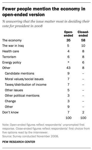
Researchers will sometimes conduct a pilot study using open-ended questions to discover which answers are most common. They will then develop closed-ended questions based off that pilot study that include the most common responses as answer choices. In this way, the questions may better reflect what the public is thinking, how they view a particular issue, or bring certain issues to light that the researchers may not have been aware of.
When asking closed-ended questions, the choice of options provided, how each option is described, the number of response options offered, and the order in which options are read can all influence how people respond. One example of the impact of how categories are defined can be found in a Pew Research Center poll conducted in January 2002. When half of the sample was asked whether it was “more important for President Bush to focus on domestic policy or foreign policy,” 52% chose domestic policy while only 34% said foreign policy. When the category “foreign policy” was narrowed to a specific aspect – “the war on terrorism” – far more people chose it; only 33% chose domestic policy while 52% chose the war on terrorism.
In most circumstances, the number of answer choices should be kept to a relatively small number – just four or perhaps five at most – especially in telephone surveys. Psychological research indicates that people have a hard time keeping more than this number of choices in mind at one time. When the question is asking about an objective fact and/or demographics, such as the religious affiliation of the respondent, more categories can be used. In fact, they are encouraged to ensure inclusivity. For example, Pew Research Center’s standard religion questions include more than 12 different categories, beginning with the most common affiliations (Protestant and Catholic). Most respondents have no trouble with this question because they can expect to see their religious group within that list in a self-administered survey.
In addition to the number and choice of response options offered, the order of answer categories can influence how people respond to closed-ended questions. Research suggests that in telephone surveys respondents more frequently choose items heard later in a list (a “recency effect”), and in self-administered surveys, they tend to choose items at the top of the list (a “primacy” effect).
Because of concerns about the effects of category order on responses to closed-ended questions, many sets of response options in Pew Research Center’s surveys are programmed to be randomized to ensure that the options are not asked in the same order for each respondent. Rotating or randomizing means that questions or items in a list are not asked in the same order to each respondent. Answers to questions are sometimes affected by questions that precede them. By presenting questions in a different order to each respondent, we ensure that each question gets asked in the same context as every other question the same number of times (e.g., first, last or any position in between). This does not eliminate the potential impact of previous questions on the current question, but it does ensure that this bias is spread randomly across all of the questions or items in the list. For instance, in the example discussed above about what issue mattered most in people’s vote, the order of the five issues in the closed-ended version of the question was randomized so that no one issue appeared early or late in the list for all respondents. Randomization of response items does not eliminate order effects, but it does ensure that this type of bias is spread randomly.
Questions with ordinal response categories – those with an underlying order (e.g., excellent, good, only fair, poor OR very favorable, mostly favorable, mostly unfavorable, very unfavorable) – are generally not randomized because the order of the categories conveys important information to help respondents answer the question. Generally, these types of scales should be presented in order so respondents can easily place their responses along the continuum, but the order can be reversed for some respondents. For example, in one of Pew Research Center’s questions about abortion, half of the sample is asked whether abortion should be “legal in all cases, legal in most cases, illegal in most cases, illegal in all cases,” while the other half of the sample is asked the same question with the response categories read in reverse order, starting with “illegal in all cases.” Again, reversing the order does not eliminate the recency effect but distributes it randomly across the population.
Question wording
The choice of words and phrases in a question is critical in expressing the meaning and intent of the question to the respondent and ensuring that all respondents interpret the question the same way. Even small wording differences can substantially affect the answers people provide.
[View more Methods 101 Videos ]
An example of a wording difference that had a significant impact on responses comes from a January 2003 Pew Research Center survey. When people were asked whether they would “favor or oppose taking military action in Iraq to end Saddam Hussein’s rule,” 68% said they favored military action while 25% said they opposed military action. However, when asked whether they would “favor or oppose taking military action in Iraq to end Saddam Hussein’s rule even if it meant that U.S. forces might suffer thousands of casualties, ” responses were dramatically different; only 43% said they favored military action, while 48% said they opposed it. The introduction of U.S. casualties altered the context of the question and influenced whether people favored or opposed military action in Iraq.
There has been a substantial amount of research to gauge the impact of different ways of asking questions and how to minimize differences in the way respondents interpret what is being asked. The issues related to question wording are more numerous than can be treated adequately in this short space, but below are a few of the important things to consider:
First, it is important to ask questions that are clear and specific and that each respondent will be able to answer. If a question is open-ended, it should be evident to respondents that they can answer in their own words and what type of response they should provide (an issue or problem, a month, number of days, etc.). Closed-ended questions should include all reasonable responses (i.e., the list of options is exhaustive) and the response categories should not overlap (i.e., response options should be mutually exclusive). Further, it is important to discern when it is best to use forced-choice close-ended questions (often denoted with a radio button in online surveys) versus “select-all-that-apply” lists (or check-all boxes). A 2019 Center study found that forced-choice questions tend to yield more accurate responses, especially for sensitive questions. Based on that research, the Center generally avoids using select-all-that-apply questions.
It is also important to ask only one question at a time. Questions that ask respondents to evaluate more than one concept (known as double-barreled questions) – such as “How much confidence do you have in President Obama to handle domestic and foreign policy?” – are difficult for respondents to answer and often lead to responses that are difficult to interpret. In this example, it would be more effective to ask two separate questions, one about domestic policy and another about foreign policy.
In general, questions that use simple and concrete language are more easily understood by respondents. It is especially important to consider the education level of the survey population when thinking about how easy it will be for respondents to interpret and answer a question. Double negatives (e.g., do you favor or oppose not allowing gays and lesbians to legally marry) or unfamiliar abbreviations or jargon (e.g., ANWR instead of Arctic National Wildlife Refuge) can result in respondent confusion and should be avoided.
Similarly, it is important to consider whether certain words may be viewed as biased or potentially offensive to some respondents, as well as the emotional reaction that some words may provoke. For example, in a 2005 Pew Research Center survey, 51% of respondents said they favored “making it legal for doctors to give terminally ill patients the means to end their lives,” but only 44% said they favored “making it legal for doctors to assist terminally ill patients in committing suicide.” Although both versions of the question are asking about the same thing, the reaction of respondents was different. In another example, respondents have reacted differently to questions using the word “welfare” as opposed to the more generic “assistance to the poor.” Several experiments have shown that there is much greater public support for expanding “assistance to the poor” than for expanding “welfare.”
We often write two versions of a question and ask half of the survey sample one version of the question and the other half the second version. Thus, we say we have two forms of the questionnaire. Respondents are assigned randomly to receive either form, so we can assume that the two groups of respondents are essentially identical. On questions where two versions are used, significant differences in the answers between the two forms tell us that the difference is a result of the way we worded the two versions.
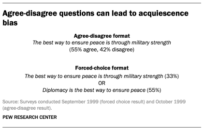
One of the most common formats used in survey questions is the “agree-disagree” format. In this type of question, respondents are asked whether they agree or disagree with a particular statement. Research has shown that, compared with the better educated and better informed, less educated and less informed respondents have a greater tendency to agree with such statements. This is sometimes called an “acquiescence bias” (since some kinds of respondents are more likely to acquiesce to the assertion than are others). This behavior is even more pronounced when there’s an interviewer present, rather than when the survey is self-administered. A better practice is to offer respondents a choice between alternative statements. A Pew Research Center experiment with one of its routinely asked values questions illustrates the difference that question format can make. Not only does the forced choice format yield a very different result overall from the agree-disagree format, but the pattern of answers between respondents with more or less formal education also tends to be very different.
One other challenge in developing questionnaires is what is called “social desirability bias.” People have a natural tendency to want to be accepted and liked, and this may lead people to provide inaccurate answers to questions that deal with sensitive subjects. Research has shown that respondents understate alcohol and drug use, tax evasion and racial bias. They also may overstate church attendance, charitable contributions and the likelihood that they will vote in an election. Researchers attempt to account for this potential bias in crafting questions about these topics. For instance, when Pew Research Center surveys ask about past voting behavior, it is important to note that circumstances may have prevented the respondent from voting: “In the 2012 presidential election between Barack Obama and Mitt Romney, did things come up that kept you from voting, or did you happen to vote?” The choice of response options can also make it easier for people to be honest. For example, a question about church attendance might include three of six response options that indicate infrequent attendance. Research has also shown that social desirability bias can be greater when an interviewer is present (e.g., telephone and face-to-face surveys) than when respondents complete the survey themselves (e.g., paper and web surveys).
Lastly, because slight modifications in question wording can affect responses, identical question wording should be used when the intention is to compare results to those from earlier surveys. Similarly, because question wording and responses can vary based on the mode used to survey respondents, researchers should carefully evaluate the likely effects on trend measurements if a different survey mode will be used to assess change in opinion over time.
Question order
Once the survey questions are developed, particular attention should be paid to how they are ordered in the questionnaire. Surveyors must be attentive to how questions early in a questionnaire may have unintended effects on how respondents answer subsequent questions. Researchers have demonstrated that the order in which questions are asked can influence how people respond; earlier questions can unintentionally provide context for the questions that follow (these effects are called “order effects”).
One kind of order effect can be seen in responses to open-ended questions. Pew Research Center surveys generally ask open-ended questions about national problems, opinions about leaders and similar topics near the beginning of the questionnaire. If closed-ended questions that relate to the topic are placed before the open-ended question, respondents are much more likely to mention concepts or considerations raised in those earlier questions when responding to the open-ended question.
For closed-ended opinion questions, there are two main types of order effects: contrast effects ( where the order results in greater differences in responses), and assimilation effects (where responses are more similar as a result of their order).
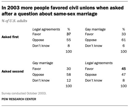
An example of a contrast effect can be seen in a Pew Research Center poll conducted in October 2003, a dozen years before same-sex marriage was legalized in the U.S. That poll found that people were more likely to favor allowing gays and lesbians to enter into legal agreements that give them the same rights as married couples when this question was asked after one about whether they favored or opposed allowing gays and lesbians to marry (45% favored legal agreements when asked after the marriage question, but 37% favored legal agreements without the immediate preceding context of a question about same-sex marriage). Responses to the question about same-sex marriage, meanwhile, were not significantly affected by its placement before or after the legal agreements question.
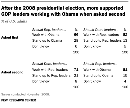
Another experiment embedded in a December 2008 Pew Research Center poll also resulted in a contrast effect. When people were asked “All in all, are you satisfied or dissatisfied with the way things are going in this country today?” immediately after having been asked “Do you approve or disapprove of the way George W. Bush is handling his job as president?”; 88% said they were dissatisfied, compared with only 78% without the context of the prior question.
Responses to presidential approval remained relatively unchanged whether national satisfaction was asked before or after it. A similar finding occurred in December 2004 when both satisfaction and presidential approval were much higher (57% were dissatisfied when Bush approval was asked first vs. 51% when general satisfaction was asked first).
Several studies also have shown that asking a more specific question before a more general question (e.g., asking about happiness with one’s marriage before asking about one’s overall happiness) can result in a contrast effect. Although some exceptions have been found, people tend to avoid redundancy by excluding the more specific question from the general rating.
Assimilation effects occur when responses to two questions are more consistent or closer together because of their placement in the questionnaire. We found an example of an assimilation effect in a Pew Research Center poll conducted in November 2008 when we asked whether Republican leaders should work with Obama or stand up to him on important issues and whether Democratic leaders should work with Republican leaders or stand up to them on important issues. People were more likely to say that Republican leaders should work with Obama when the question was preceded by the one asking what Democratic leaders should do in working with Republican leaders (81% vs. 66%). However, when people were first asked about Republican leaders working with Obama, fewer said that Democratic leaders should work with Republican leaders (71% vs. 82%).
The order questions are asked is of particular importance when tracking trends over time. As a result, care should be taken to ensure that the context is similar each time a question is asked. Modifying the context of the question could call into question any observed changes over time (see measuring change over time for more information).
A questionnaire, like a conversation, should be grouped by topic and unfold in a logical order. It is often helpful to begin the survey with simple questions that respondents will find interesting and engaging. Throughout the survey, an effort should be made to keep the survey interesting and not overburden respondents with several difficult questions right after one another. Demographic questions such as income, education or age should not be asked near the beginning of a survey unless they are needed to determine eligibility for the survey or for routing respondents through particular sections of the questionnaire. Even then, it is best to precede such items with more interesting and engaging questions. One virtue of survey panels like the ATP is that demographic questions usually only need to be asked once a year, not in each survey.
U.S. Surveys
Other research methods, sign up for our weekly newsletter.
Fresh data delivered Saturday mornings
1615 L St. NW, Suite 800 Washington, DC 20036 USA (+1) 202-419-4300 | Main (+1) 202-857-8562 | Fax (+1) 202-419-4372 | Media Inquiries
Research Topics
- Age & Generations
- Coronavirus (COVID-19)
- Economy & Work
- Family & Relationships
- Gender & LGBTQ
- Immigration & Migration
- International Affairs
- Internet & Technology
- Methodological Research
- News Habits & Media
- Non-U.S. Governments
- Other Topics
- Politics & Policy
- Race & Ethnicity
- Email Newsletters
ABOUT PEW RESEARCH CENTER Pew Research Center is a nonpartisan fact tank that informs the public about the issues, attitudes and trends shaping the world. It conducts public opinion polling, demographic research, media content analysis and other empirical social science research. Pew Research Center does not take policy positions. It is a subsidiary of The Pew Charitable Trusts .
Copyright 2024 Pew Research Center
Terms & Conditions
Privacy Policy
Cookie Settings
Reprints, Permissions & Use Policy

AI + Machine Learning , Announcements , Azure AI , Azure AI Studio
Introducing Phi-3: Redefining what’s possible with SLMs
By Misha Bilenko Corporate Vice President, Microsoft GenAI
Posted on April 23, 2024 4 min read
- Tag: Copilot
- Tag: Generative AI
We are excited to introduce Phi-3, a family of open AI models developed by Microsoft. Phi-3 models are the most capable and cost-effective small language models (SLMs) available, outperforming models of the same size and next size up across a variety of language, reasoning, coding, and math benchmarks. This release expands the selection of high-quality models for customers, offering more practical choices as they compose and build generative AI applications.
Starting today, Phi-3-mini , a 3.8B language model is available on Microsoft Azure AI Studio , Hugging Face , and Ollama .
- Phi-3-mini is available in two context-length variants—4K and 128K tokens. It is the first model in its class to support a context window of up to 128K tokens, with little impact on quality.
- It is instruction-tuned, meaning that it’s trained to follow different types of instructions reflecting how people normally communicate. This ensures the model is ready to use out-of-the-box.
- It is available on Azure AI to take advantage of the deploy-eval-finetune toolchain, and is available on Ollama for developers to run locally on their laptops.
- It has been optimized for ONNX Runtime with support for Windows DirectML along with cross-platform support across graphics processing unit (GPU), CPU, and even mobile hardware.
- It is also available as an NVIDIA NIM microservice with a standard API interface that can be deployed anywhere. And has been optimized for NVIDIA GPUs .
In the coming weeks, additional models will be added to Phi-3 family to offer customers even more flexibility across the quality-cost curve. Phi-3-small (7B) and Phi-3-medium (14B) will be available in the Azure AI model catalog and other model gardens shortly.
Microsoft continues to offer the best models across the quality-cost curve and today’s Phi-3 release expands the selection of models with state-of-the-art small models.

Azure AI Studio
Phi-3-mini is now available
Groundbreaking performance at a small size
Phi-3 models significantly outperform language models of the same and larger sizes on key benchmarks (see benchmark numbers below, higher is better). Phi-3-mini does better than models twice its size, and Phi-3-small and Phi-3-medium outperform much larger models, including GPT-3.5T.
All reported numbers are produced with the same pipeline to ensure that the numbers are comparable. As a result, these numbers may differ from other published numbers due to slight differences in the evaluation methodology. More details on benchmarks are provided in our technical paper .
Note: Phi-3 models do not perform as well on factual knowledge benchmarks (such as TriviaQA) as the smaller model size results in less capacity to retain facts.
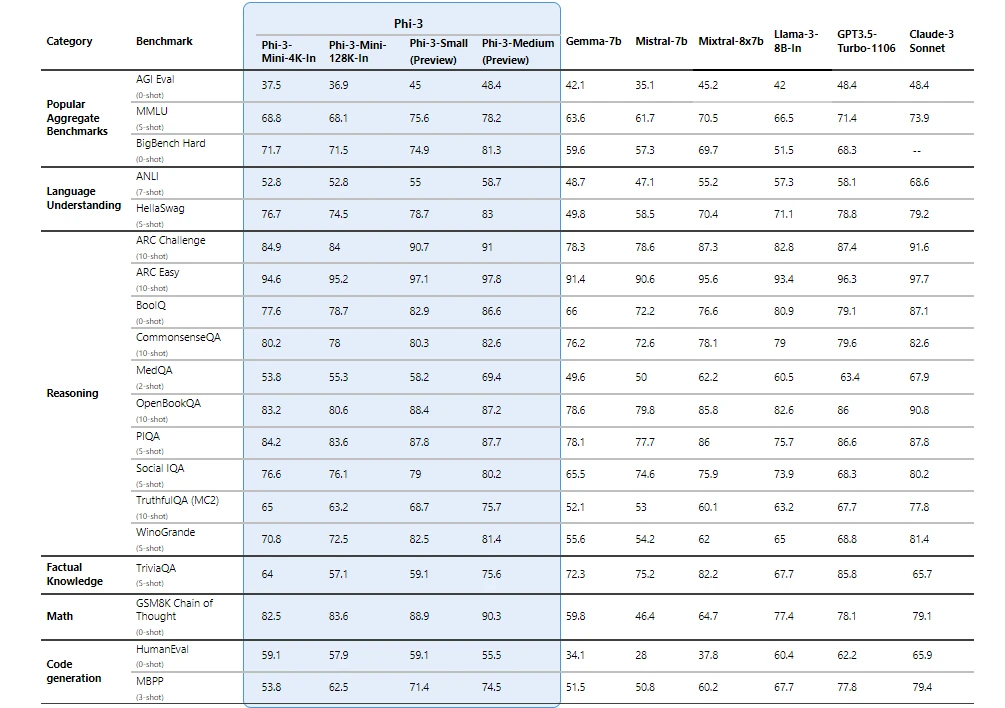
Safety-first model design
Responsible ai principles
Phi-3 models were developed in accordance with the Microsoft Responsible AI Standard , which is a company-wide set of requirements based on the following six principles: accountability, transparency, fairness, reliability and safety, privacy and security, and inclusiveness. Phi-3 models underwent rigorous safety measurement and evaluation, red-teaming, sensitive use review, and adherence to security guidance to help ensure that these models are responsibly developed, tested, and deployed in alignment with Microsoft’s standards and best practices.
Building on our prior work with Phi models (“ Textbooks Are All You Need ”), Phi-3 models are also trained using high-quality data. They were further improved with extensive safety post-training, including reinforcement learning from human feedback (RLHF), automated testing and evaluations across dozens of harm categories, and manual red-teaming. Our approach to safety training and evaluations are detailed in our technical paper , and we outline recommended uses and limitations in the model cards. See the model card collection .
Unlocking new capabilities
Microsoft’s experience shipping copilots and enabling customers to transform their businesses with generative AI using Azure AI has highlighted the growing need for different-size models across the quality-cost curve for different tasks. Small language models, like Phi-3, are especially great for:
- Resource constrained environments including on-device and offline inference scenarios.
- Latency bound scenarios where fast response times are critical.
- Cost constrained use cases, particularly those with simpler tasks.
For more on small language models, see our Microsoft Source Blog .
Thanks to their smaller size, Phi-3 models can be used in compute-limited inference environments. Phi-3-mini, in particular, can be used on-device, especially when further optimized with ONNX Runtime for cross-platform availability. The smaller size of Phi-3 models also makes fine-tuning or customization easier and more affordable. In addition, their lower computational needs make them a lower cost option with much better latency. The longer context window enables taking in and reasoning over large text content—documents, web pages, code, and more. Phi-3-mini demonstrates strong reasoning and logic capabilities, making it a good candidate for analytical tasks.
Customers are already building solutions with Phi-3. One example where Phi-3 is already demonstrating value is in agriculture, where internet might not be readily accessible. Powerful small models like Phi-3 along with Microsoft copilot templates are available to farmers at the point of need and provide the additional benefit of running at reduced cost, making AI technologies even more accessible.
ITC, a leading business conglomerate based in India, is leveraging Phi-3 as part of their continued collaboration with Microsoft on the copilot for Krishi Mitra, a farmer-facing app that reaches over a million farmers.
“ Our goal with the Krishi Mitra copilot is to improve efficiency while maintaining the accuracy of a large language model. We are excited to partner with Microsoft on using fine-tuned versions of Phi-3 to meet both our goals—efficiency and accuracy! ” Saif Naik, Head of Technology, ITCMAARS
Originating in Microsoft Research, Phi models have been broadly used, with Phi-2 downloaded over 2 million times. The Phi series of models have achieved remarkable performance with strategic data curation and innovative scaling. Starting with Phi-1, a model used for Python coding, to Phi-1.5, enhancing reasoning and understanding, and then to Phi-2, a 2.7 billion-parameter model outperforming those up to 25 times its size in language comprehension. 1 Each iteration has leveraged high-quality training data and knowledge transfer techniques to challenge conventional scaling laws.
Get started today
To experience Phi-3 for yourself, start with playing with the model on Azure AI Playground . You can also find the model on the Hugging Chat playground . Start building with and customizing Phi-3 for your scenarios using the Azure AI Studio . Join us to learn more about Phi-3 during a special live stream of the AI Show.
1 Microsoft Research Blog, Phi-2: The surprising power of small language models, December 12, 2023 .
Let us know what you think of Azure and what you would like to see in the future.
Provide feedback
Build your cloud computing and Azure skills with free courses by Microsoft Learn.
Explore Azure learning
Related posts
AI + Machine Learning , Azure AI , Azure AI Content Safety , Azure Cognitive Search , Azure Kubernetes Service (AKS) , Azure OpenAI Service , Customer stories
AI-powered dialogues: Global telecommunications with Azure OpenAI Service chevron_right
AI + Machine Learning , Azure AI , Azure AI Content Safety , Azure OpenAI Service , Customer stories
Generative AI and the path to personalized medicine with Microsoft Azure chevron_right
AI + Machine Learning , Azure AI , Azure AI Services , Azure AI Studio , Azure OpenAI Service , Best practices
AI study guide: The no-cost tools from Microsoft to jump start your generative AI journey chevron_right
AI + Machine Learning , Azure AI , Azure VMware Solution , Events , Microsoft Copilot for Azure , Microsoft Defender for Cloud
Get ready for AI at the Migrate to Innovate digital event chevron_right

Image Manipulation in Research Articles
Advanced technologies have put the control of scientific images in the hands of researchers and authors. For example, the blots and gels that accompany and represent data in an article, may be manipulated in a variety of ways. However, there are two basic categories of image manipulation or image editing in scientific research articles:
1) Clarification
2) Deception
In clarification, an author may, quite ethically, attempt to “clean up” an image in order for it to be more readable. Image editing software programs, such as Adobe Photoshop, allow for the digital manipulation of an image to highlight the areas of interest and diminish the areas that distract from the relevant information. However, if the author fails to note that the image has been altered, this could lead to trouble—the author could be accused of misconduct and the journal could be accused of publishing inaccurate or misleading material.
Deception, on the other hand, is quite straightforward. If the data does not match the author’s conclusion, the author may edit the accompanying image or images to match the claims. With the pressure to publish being intense at many universities, it would be quite tempting to tweak an image to go along with findings that, perhaps, aren’t completely valid. In this case, there is a lot more than reputation at stake in the scientific world if the deception is not caught.
Since 2002, many journals and publishers have begun allowing authors to submit their work electronically. Coupled with this advancement and wide distribution/usage of image editing software, the stage was set for an increase in the manipulation of scientific images.
Elisabeth Bik, Arturo Casadevall, and Ferric Fang co-authored a paper titled, “The Prevalence of Inappropriate Image Duplication in Biomedical Research Publications”, that studied the prevalence of image manipulation in scientific research publications. They screened 20,621 scientific papers from 40 journals dating from 1995-2014 and found that 782 of those papers (3.8%) contained at least one figure with a manipulated image. They also found that incidences increased after 2003.
Who is Responsible?
Responsibility for ethical and accurate data representation in scientific images lies mainly with the author. However, peer-reviewers must be vigilant, and journal editors must be the final gateway—setting clear guidelines for authors, spending the time and money to thoroughly review and investigate article submissions, and following through with consequences for clear cases of image manipulation.
Here is an example of clear manipulation of data from the Journal of Cell Biology :

Although moving into the electronic age may have made some areas of publication easier for academic journals, however, this is one area where there will be no substitute for the investment of time for inquiry and funding for the appropriate investigative tools. It all hinges upon the establishment of clear guidelines for authors so that there is no question about what is acceptable and unacceptable manipulation of scientific images.
Guidelines and Investigative Tools
Along with the guidelines for authors, reviewers, and publishers, even investigative tools that keep pace with digital image editing software are needed. These guidelines regarding image manipulation should be a standard part of article submission guidelines for authors. In addition, there should be guidelines for peer reviewers and journal editors so that they know what to look for when they are examining data in the form of an image.
The Council of Science Editors (CSE) has published some guidelines set forth by the Rockefeller University Press, which outlines acceptable and unacceptable image manipulation. The CSE has also developed a procedure for “Handling Guideline Violations,” intended to provide direction to reviewers and journal editors. The CSE emphasizes that guidelines will serve no purpose if editors are not willing to follow through with repercussions for misconduct.
Investigative tools will also need to be made available as widely as image editing software. John Dahlberg, PhD, Deputy Director of the Office of Research Integrity (a division of the US Government’s Department of Health and Human Services), gives examples of some forensic image tools in an article by Anthony Newman, published by Elsevier:
- Forensic Droplets – A small desktop application in Adobe Photoshop that can be used to compare two black and white scientific images, and can detect image editing
- Adobe Bridge – Digital asset manager that allows the user to efficiently locate, organize, browse, preview, and batch process content files
- ImageJ – Public domain Java image processing program, which allows multiple images to be displayed on the screen at one time
Solutions for Image Manipulation
In 2006, Mike Rossner wrote about a case of image fraud for The Scientist . In reading the article, one can sense his annoyance regarding a case of image fraud perpetrated by Woo-Suk Hwang. He makes a clear case for setting and enforcing guidelines and the usage of image fraud-detecting technology for all scientific research submissions.
Mike has now gone on to establish his own company, dedicated to the issue of image manipulation— Image Data Integrity (IDI). The company provides “consultation for concerns related to biomedical image data manipulation for institutions, journal, funding agencies, and legal counselors.” The fact that someone in the field of scientific research has gone on to establish an entire company around this issue indicates that image manipulation is a problem that is not likely to go away soon. Constant vigilance is required.
Journal editors need to make guidelines clear to authors about acceptable and unacceptable image editing. They should make it clear that there will be consequences for knowingly and purposefully manipulating images in an unethical fashion.

Thanks for sharing this kind of articles.
Rate this article Cancel Reply
Your email address will not be published.

Enago Academy's Most Popular Articles

- AI in Academia
- Industry News
Controversy Erupts Over AI-Generated Visuals in Scientific Publications
In recent months, the scientific community has been grappling with a growing trend: the integration…

Science under Surveillance: Journals adopt advanced AI to uncover image manipulation
Journals are increasingly turning to cutting-edge AI tools to uncover deceitful images published in manuscripts.…
- Old Webinars
- Webinar Mobile App
How to Avoid Fraudulent Image Manipulation
What is image manipulation? Best practices for image processing Avoiding image manipulation Tools for detecting…

- Figures & Tables
- Reporting Research
Scientific Fraud: How Journals Detect Image Manipulation (Part 2)
In the first part of this series, we highlighted the challenges and takes from authors…

Scientific Fraud: How Journals Detect Image Manipulation (Part 1)
In 2009, researcher Hwang Woo-Suk was convicted of research misconduct that included embezzlement and unethical…
How to Avoid Image Manipulation in Research Papers
Is Your Image the Whole Truth?

Sign-up to read more
Subscribe for free to get unrestricted access to all our resources on research writing and academic publishing including:
- 2000+ blog articles
- 50+ Webinars
- 10+ Expert podcasts
- 50+ Infographics
- 10+ Checklists
- Research Guides
We hate spam too. We promise to protect your privacy and never spam you.
I am looking for Editing/ Proofreading services for my manuscript Tentative date of next journal submission:

What should universities' stance be on AI tools in research and academic writing?
Planet versus Plastics
Plastic waste has infiltrated every corner of our planet, from oceans and waterways to the food chain and even our bodies. Only 9% of plastic is recycled due to factors including poor infrastructure, technical challenges, lack of incentives, and low market demand.
“We need legislation that disincentivizes big oil from producing plastic in the first place, coupled with enforced single use plastic taxes and fines,” says Desiree LaBeaud , professor of pediatric infectious diseases and senior fellow at Stanford Woods Institute for the Environment . “We also need truly compostable alternatives that maintain the convenient lifestyle that plastic allows us now."
Plastic presents a problem like no other. Stanford scholars are approaching it from many angles: exploring the connection between plastic and disease, rethinking how plastic could be reused, and uncovering new ways of breaking down waste. In honor of Earth Day and this year’s theme – Planet vs. Plastics – we’ve highlighted stories about promising solutions to the plastics challenge.
Environmental changes are altering the risk for mosquito-borne diseases

Our changing climate is dramatically altering the landscape for mosquito-borne diseases, but other changes to the physical environment - like the proliferation of plastic trash - also make an impact, as mosquitos can breed in the plastic waste we discard.
Since this study published, HERI-Kenya , a nonprofit started by Stanford infectious disease physician Desiree LaBeaud , has launched HERI Hub , a brick and mortar education hub that educates, empowers and inspires community members to improve the local environment to promote health.
Using plastic waste to build roads, buildings, and more

Stanford engineers Michael Lepech and Zhiye Li have a unique vision of the future: buildings and roads made from plastic waste. In this story, they discuss obstacles, opportunities, and other aspects of transforming or upcycling plastic waste into valuable materials.
Since this white paper was published, students in Lepech's life cycle assessment course have explored the environmental and economic impacts of waste management, emissions, and energy efficiency of building materials for the San Francisco Museum of Modern Arts. In addition to recycled plastic, they proposed a photovoltaic system and conducted comparison studies to maximize the system’s life cycle. This work is being translated into an upcoming publication.
Stanford researchers show that mealworms can safely consume toxic additive-containing plastic

Mealworms are not only able to eat various forms of plastic, as previous research has shown, they can also consume potentially toxic plastic additives in polystyrene with no ill effects. The worms can then be used as a safe, protein-rich feed supplement.
Since this study published, it has inspired students across the world to learn about and experiment with mealworms and plastic waste. Stanford researchers involved with this and related studies have been inundated with requests for more information and guidance from people inspired by the potential solution.
Grants tackle the plastics problem
Stanford Woods Institute has awarded more than $23 million in funding to research projects that seek to identify solutions to pressing environment and sustainability challenges, including new approaches to plastic waste management.
Converting polyethylene into palm oil

This project is developing a new technology to convert polyethylene — by far the most discarded plastic — into palm oil. The approach could add value to the plastic waste management chain while sourcing palm oil through a less destructive route.
Improving plastic waste management

This project aims to radically change the way plastic waste is processed via a new biotechnology paradigm: engineering highly active enzymes and microbes capable of breaking down polyesters in a decentralized network of “living” waste receptacles.
More stories from Stanford
Eight simple but meaningful things you can do for the environment.

A new, artistic perspective on plastic waste

Whales eat colossal amounts of microplastics

Event | Pollution and Health

A greener future begins with small steps

Mosquito diseases on the move

Last straw: The path to reducing plastic pollution

Plastic ingestion by fish a growing problem

Stanford infectious disease expert Desiree LaBeaud talks trash, literally, on Stanford Engineering's The Future of Everything podcast.
Help | Advanced Search
Computer Science > Computer Vision and Pattern Recognition
Title: research on splicing image detection algorithms based on natural image statistical characteristics.
Abstract: With the development and widespread application of digital image processing technology, image splicing has become a common method of image manipulation, raising numerous security and legal issues. This paper introduces a new splicing image detection algorithm based on the statistical characteristics of natural images, aimed at improving the accuracy and efficiency of splicing image detection. By analyzing the limitations of traditional methods, we have developed a detection framework that integrates advanced statistical analysis techniques and machine learning methods. The algorithm has been validated using multiple public datasets, showing high accuracy in detecting spliced edges and locating tampered areas, as well as good robustness. Additionally, we explore the potential applications and challenges faced by the algorithm in real-world scenarios. This research not only provides an effective technological means for the field of image tampering detection but also offers new ideas and methods for future related research.
Submission history
Access paper:.
- Other Formats
References & Citations
- Google Scholar
- Semantic Scholar
BibTeX formatted citation
Bibliographic and Citation Tools
Code, data and media associated with this article, recommenders and search tools.
- Institution
arXivLabs: experimental projects with community collaborators
arXivLabs is a framework that allows collaborators to develop and share new arXiv features directly on our website.
Both individuals and organizations that work with arXivLabs have embraced and accepted our values of openness, community, excellence, and user data privacy. arXiv is committed to these values and only works with partners that adhere to them.
Have an idea for a project that will add value for arXiv's community? Learn more about arXivLabs .
IMAGES
VIDEO
COMMENTS
Finally, while a lot of data is helpful to have, be sure to reduce the presence of "chartjunk" - the unnecessary visual elements that distract the reader from what really matters…your data! There are various tools/platforms to help you create high-quality images for research papers including R, ImageJ, ImageMagick, Cytospace, and more.
BioRender has revolutionized the way we draw and communicate our science. Because of the large number of pre-drawn icons and color schemes to choose from, I can create beautiful images that accurately depict our scientific findings in no time. I don't know what I would do without BioRender. My 'circles and square figure' days in PowerPoint are ...
1. Editable Images. The best kind of science images are editable vector files that allow you to customize the designs to best match the main points of your research. These include image file types such as Scalable Vector Graphics (.svg), Adobe Illustrator (.ai), Affinity Designer (.afdesign), Encapsulated PostScript (.eps), and some files in ...
The guide's focus is on digital photo editing and the production of figures using Adobe Photoshop to produce publication-quality figures for scientific publications.
Often, raster images have a specified resolution stored separately from the pixel values (a.k.a. metadata).This resolution metadata isn't really an integral part of the raster image, though it can be useful for conveying important information, such as the scale factor of a microscope or the physical size at which an image is intended to be printed. . Similarly, vector images may use a physical ...
Adobe Illustrator is another popular image editing software. It is a vector-based drawing program that allows the user to import images, create drawings, and align multiple images into one figure. The figure that is generated can be exported as a high-resolution image that is ready for publication. Illustrator allows the user to fully customize ...
Fortunately, we have several tools that can help us effectively prepare or improvise them. Here we give you a summary of the top tools that can be used to create images and figures for scientific research publications. You can also access detailed information on some of these tools here. SmartShorts. 5 stars 4 stars 3 stars 2 stars 1 star.
Figures for scientific publications go through various stages from the planning, to the capturing of images, to the production of finished figures for publication. This guide is meant to familiarise the reader with the main image-editing software used by professional photographers. The guide's focus is on digital photo editing and the production of figures using Adobe Photoshop to produce ...
Here, three researchers share their advice on how to create sci¬entific figures that are both accurate and engaging. 1. Use an image-processing workflow. Through her experience teaching visual ...
Images: Although many web-based images often appear at very low resolutions, readers will benefit most from your research if your images offer high-resolution detail. 300 dpi. Any, as long as it is legible to the editor and peer reviewers. 300 dpi. Image size. Small: Used for small line art and images that will occupy one-quarter of the page
S2 Table: Number of articles examined by journal in plant science.Values are n, or n (% of all articles). Screening was performed to exclude articles that were not full-length original research articles (e.g., reviews, editorials, perspectives, commentaries, letters to the editor, short communications, etc.), were not published in April 2018, or did not include eligible images.
Images in scientific writing. Images provide a pictorial insight into the research when appropriately used. Images alter the initial perception of professional editors and reviewers while assessing the manuscript. [ 1, 2] It is essential to display images that are more relevant and explanatory to the text with a precise legend that could make ...
First of all, taking the photos with a high-quality is important itself from for example microscope or something like that but if we have to do editing on photos I think the Photoshop software is ...
Academic Editing Services Editing and proofreading services for a publication-ready manuscript ... ethical standards. In the second video, we navigate the intricate landscape of ethics surrounding the utilization of images in research papers. This video illuminates the pivotal role images play in conveying scientific discoveries, while also ...
Click on the figure you want to change, edit or delete. Click the blue edit icon in the shape of a pencil. To replace the figure, click Replace Image in the bottom left-hand corner and select the file you want to replace it with, then click Done. If you just want to edit the caption, simply click in the caption box and edit the text, then click ...
Editing is about making changes to your sentences and surface features in your research paper. When you edit, you should check for things like grammatical errors, punctuation errors, spelling, and issues related to documentation. Too often, students think that they can edit well with one pass or count on a grammar checker to "fix ...
1- Right click on the image. 2- Save image as. 3- In Microsoft Word, choose insert picture. 4- select the saved image file. Cite. 1 Recommendation. R. Hadria. Institute of Agronomic Research. Dear ...
You can get help with research articles, reviews, and grant proprosals across the natural sciences (medicine, biology, chemistry, physics, earth sciences) and engineering, and even get a premium English-language edit, a developmental edit for content, a quality assurance edit, and a summary report.
Research Paper download EditBench (379 MB) Editing Flow. The input to Imagen Editor is a masked image and a text prompt, the output is an image with the unmasked areas untouched and the masked areas filled-in. The edits are faithful to input text prompts, while consistent with input images: ...
View PDF Abstract: We propose a method for editing images from human instructions: given an input image and a written instruction that tells the model what to do, our model follows these instructions to edit the image. To obtain training data for this problem, we combine the knowledge of two large pretrained models -- a language model (GPT-3) and a text-to-image model (Stable Diffusion) -- to ...
save, print, modify colors, and quantitate images. One of the more exciting features is its ability to generate stacks (a series of images) from videos or convert photos into videos. This is helpful for live cell imaging. Inkspace is a quality vector graphics editor that is open sourced and provides flexible drawing tools.
Writing Survey Questions. Perhaps the most important part of the survey process is the creation of questions that accurately measure the opinions, experiences and behaviors of the public. Accurate random sampling will be wasted if the information gathered is built on a shaky foundation of ambiguous or biased questions.
Organizational inefficiency and ineffectiveness are often linked to identity crises within the organizational context. This systematic review seeks to enhance the comprehension of Organizational Culture (OC) as a crucial approach to addressing such crises. The study focusses on the measurements, perspectives, and orientations of OC, providing ...
Analyze images, comprehend speech, and make predictions using data. Cloud migration and modernization. Simplify and accelerate your migration and modernization with guidance, tools, and resources. Data and analytics. Gather, store, process, analyze, and visualize data of any variety, volume, or velocity. Hybrid cloud and infrastructure
Gene editing has the potential to solve fundamental challenges in agriculture, biotechnology, and human health. CRISPR-based gene editors derived from microbes, while powerful, often show significant functional tradeoffs when ported into non-native environments, such as human cells. Artificial intelligence (AI) enabled design provides a powerful alternative with potential to bypass ...
The success of image generative models has enabled us to build methods that can edit images based on text or other user input. However, these methods are bespoke, imprecise, require additional information, or are limited to only 2D image edits. We present GeoDiffuser, a zero-shot optimization-based method that unifies common 2D and 3D image-based object editing capabilities into a single ...
However, there are two basic categories of image manipulation or image editing in scientific research articles: 1) Clarification. 2) Deception. In clarification, an author may, quite ethically, attempt to "clean up" an image in order for it to be more readable. Image editing software programs, such as Adobe Photoshop, allow for the digital ...
High-Temperature Materials Science Experiment Cabinet on the Chinese Space Station is mainly used to carry out experimental research related to high-temperature materials science in microgravity. It is equipped with an X-ray transmission imaging module, which is applied to realize transmission imaging of material samples under microgravity. However, the X-ray light source is far away from the ...
Planet versus Plastics. Plastic waste has infiltrated every corner of our planet, from oceans and waterways to the food chain and even our bodies. Only 9% of plastic is recycled due to factors including poor infrastructure, technical challenges, lack of incentives, and low market demand. "We need legislation that disincentivizes big oil from ...
With the development and widespread application of digital image processing technology, image splicing has become a common method of image manipulation, raising numerous security and legal issues. This paper introduces a new splicing image detection algorithm based on the statistical characteristics of natural images, aimed at improving the accuracy and efficiency of splicing image detection ...