Networking | Cloud | DevOps | IaC


IEEE 802.1X Authentication and Dynamic VLAN Assignment with NPS Radius Server
IEEE 802.1X Authentication and Dynamic VLAN Assignment with NPS Radius Server is an important element to networking in the real world. User location cannot be predicted as they may be at and out of a desk and up and about should they need to do so. Tying them to a local VLAN may only be helpful if they are bound to desks in those locations, although the most ideal outcome, it is not the most practical.
It is only wise to incorporate IEEE 802.1X Authentication and Dynamic VLAN Assignment with NPS Radius Server in areas where you expect different teams to come to. Meeting rooms could for a moment have the accounting group or the development group meeting there and based on the intelligent and dynamic vlan assignmnet with 802.1x authentication, users port-access are defined their appropriate vlans for their respective access to resources on the network.
How to Provision 802.1 X Authentication Step By Step With Dynamic VLAN Assignment With Windows Radius Server For 802.1x Clients.
A typical configuration for a system under IEEE 802.1x Authentication control is shown in the following figure.
In this scenario, “Lady Smith” wishes to use services offered by servers on the LAN behind the switch. There are multiple VLANs with resources available based on user vlan membership. Her laptop computer is connected to a port on the Aruba 2920 Edge Switch that has 802.1x port authentication control enabled.
The laptop computer must therefore act in a supplicant role. Message exchanges take place between the supplicant and the authenticator which is the Aruba 2920 Switch, and the authenticator passes the supplicant’s credentials which is her (Windows Active Directory User Account Credentials) to the authentication server for verification. The NPS Server which is the authentication server then informs the authenticator whether or not the authentication attempt succeeded, at which point “Lady Smith” is either granted or denied access to the LAN behind the switch.
Setup Structure for IEEE 802.1X Authentication and Dynamic VLAN Assignment with NPS Radius Server
- Supplicant: Laptop running Microsoft Windows 10 or Windows 7
- Authenticator: HP Aruba 2920 Edge Switch
- Authentication Server: Microsoft NPS (Network Policy Server) running on Windows Server 2012 R2.
- User Database : Active Directory
For Windows Infrastructure
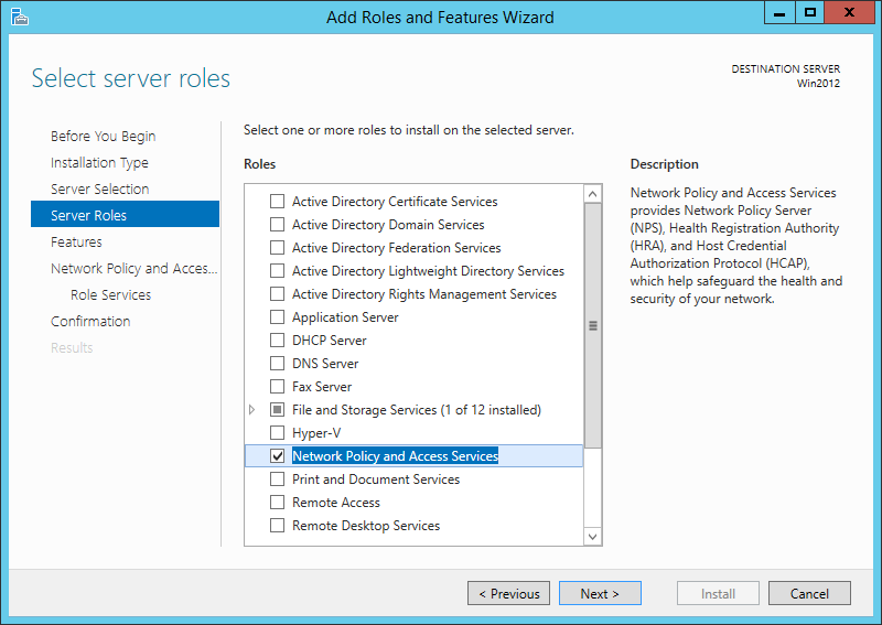
Create NPS Server – Add Role on Windows Server 2012 R2
- Create DHCP Scopes for VLANS
Create RADIUS Client on NAC using Network Policy Server
- Create Network Policies
- Configure a Network Policy for VLANs
- Start Wired Auto-Config Service
- Enable Network Authentication
Create the DHCP Scopes for VLAN100 and VLAN200 Groups
- Development Group Scope – VLAN 100
SVI: ip address 172.16.80.254 255.255.255.0 Scope Subnet: 172.16.80.1/24
- Accounting Group Scope – VLAN 200
SVI:ip address 172.16.70.254 255.255.255.0 Scope Subnet: 172.16.70.0/24
Secret Key: secret12
Add Edge Switch Management IP as the RADIUS Client
The Shared Secret Key: secret12 will be used in the Switch Configuration.
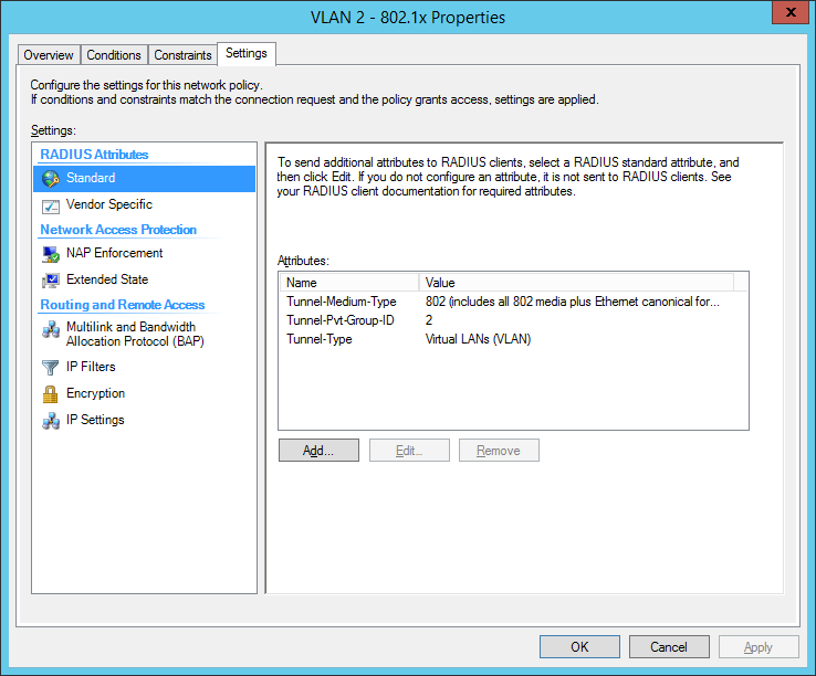
Create Network Policy Settings for Accounting Group for VLAN 200
Configuration Example
Here’s an example of how you might consider when configuring Microsoft NPS Server to assign users to a VLAN based on their user group, using NPS for the authentication and authorization of users. This configuration has worked flawlessly on the HP Aruba 2920 Switch. The key to getting this to work is the use of a RADIUS element called: ‘Tunnel-PVT-Group-ID’. This is a RADIUS attribute that may be passed back to the authenticator (i.e. the Aruba 2920 Switch) by the authentication server (i.e. Microsoft NPS Server) when a successful authentication has been achieved. There are a few other elements which need to accompany it, but this is the key element, as it specifies the VLAN number that the user should be assigned to.
The other elements that need to be returned by the NPS Server are as follows:
- Tunnel-PVT-Group-ID: 200
- Service-Type: Framed
- Tunnel-Type: VLAN
- Tunnel-Medium-Type: 802
For Client Infrastructure
On the Supplicant, Windows 7 or 10 configure the following steps on the Ethernet Adapter to enable IEEE 802.1X Authentication
For Network Infrastructure
Connect Server Infrastructure to VLAN 400
Create VLAN for Accounting Group
Create VLAN for Development Group
Create AAA Configuration on Switch for Radius Authentication
Download the Switch Configuration:
Test the IEEE 802.1X Authentication and Dynamic VLAN Assignment with NPS Radius Server
Verify Port-Access with the following user groups – VLAN 100 and VLAN 200
Think of what other clever things you can do from the information below;
Breakdown of Commands for RADIUS Authentication
Verification Commands
Thanks for reading. Please share your thoughts in the comment box below;
Published in Configuring , Design , Installing and Configuring , Networking , Security and Switching
- 802.1 x authentication step by step aruba
- 802.1 x authentication step by step cisco
- 802.1 x wireless authentication step by step
- 802.1x authentication process
- 802.1x authentication windows 10
- 802.1x authentication windows server 2012
- 802.1x certificate authentication
- assignment wlc
- cisco dot1x
- cisco ise dynamic vlan
- cisco ise dynamic vlan assignment wlc
- cisco wireless radius attributes
- configuration example
- dynamic vlan assignment cisco 2960 dynamic vlan configuration in packet tracer
- dynamic vlan assignment with windows radius server
- dynamic vlan cisco
- dynamic vlan ruckus
- meraki dynamic vlan assignment
- nps mac authentication wired
- nps policy for mac-based authentication
- radius multiple vlans
- vlan radius server
- vlan steering
- vmps server
Network Guys
Share your knowledge!
How to use 802.1x/mac-auth and dynamic VLAN assignment
Hello guys! Today I want to show you how to secure your edge-switches with 802.1x and mac-authentication fallback in combination with HPE comware-based switches. The 802.1x protocol is used for network access control. For devices like printers, cameras, etc. we will use mac-authentication as a fallback. We will also use dynamic VLAN assignment for the connected ports.
Our radius server will be Microsoft NPS. You can activate this role on the Windows server:
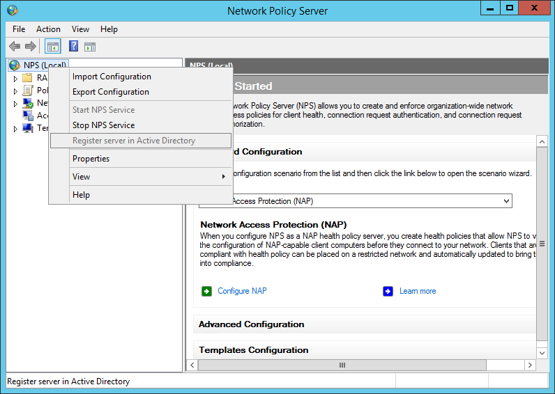
After the installation, open the NPS console and register the radius server in your Active Directory:
add your switches or your management network as a radius-client:
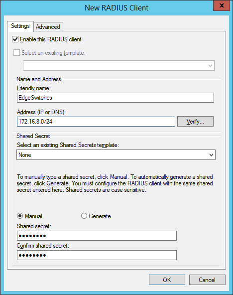
the shared secret will be used in the switch configuration. In created two groups within my test environment:
- “ VLAN2-802.1x ” containing computer accounts
- “ VLAN3-MAC-Auth ” containing user accounts (username+password = mac-address of the device)
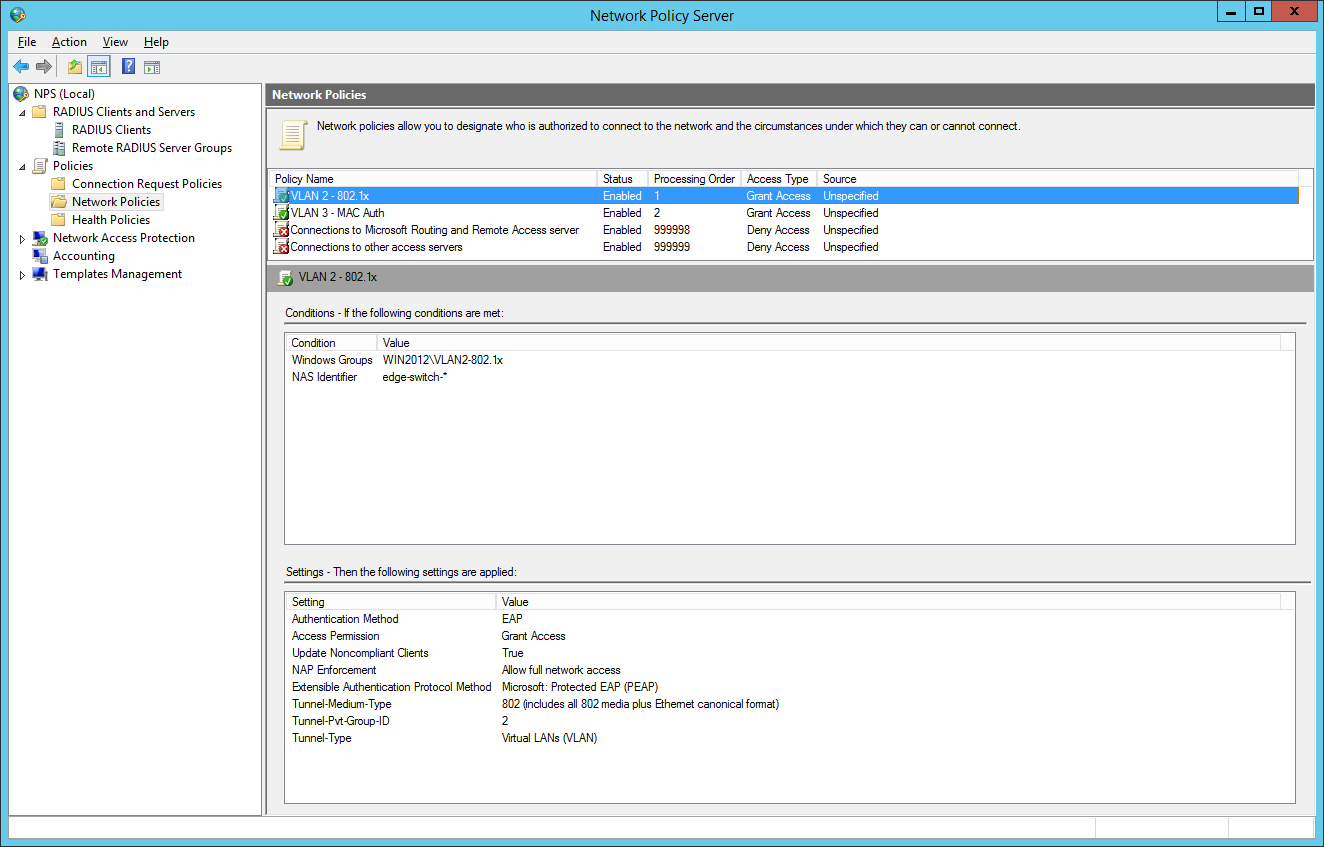
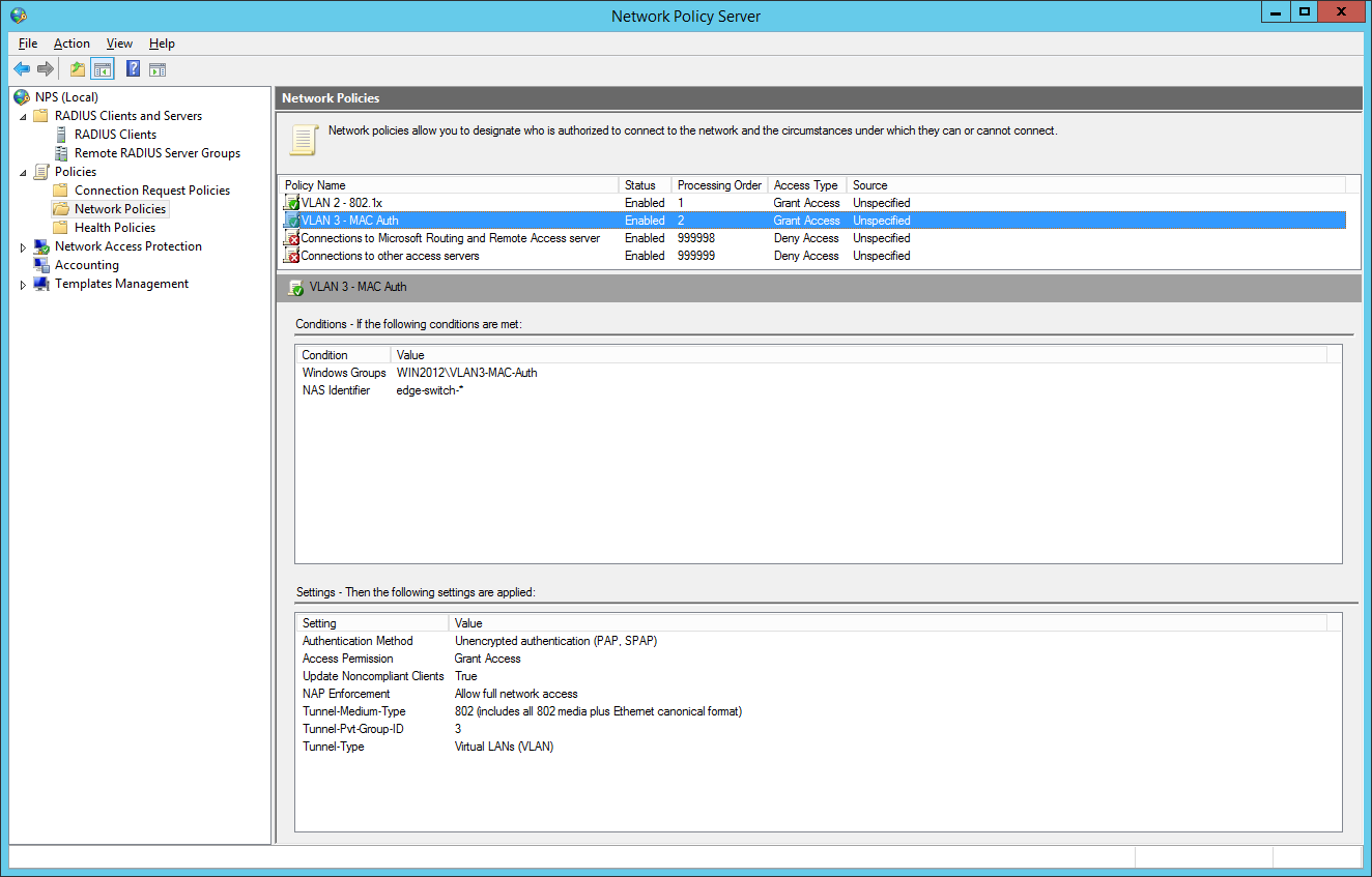
So we will now configure two network policies for our network access control:

I also configured a NAS Identifier so no other device can use the radius server. The clients will use their computer certificate so you will need a running internal certification authority. Choose PEAP only as the authentication method:
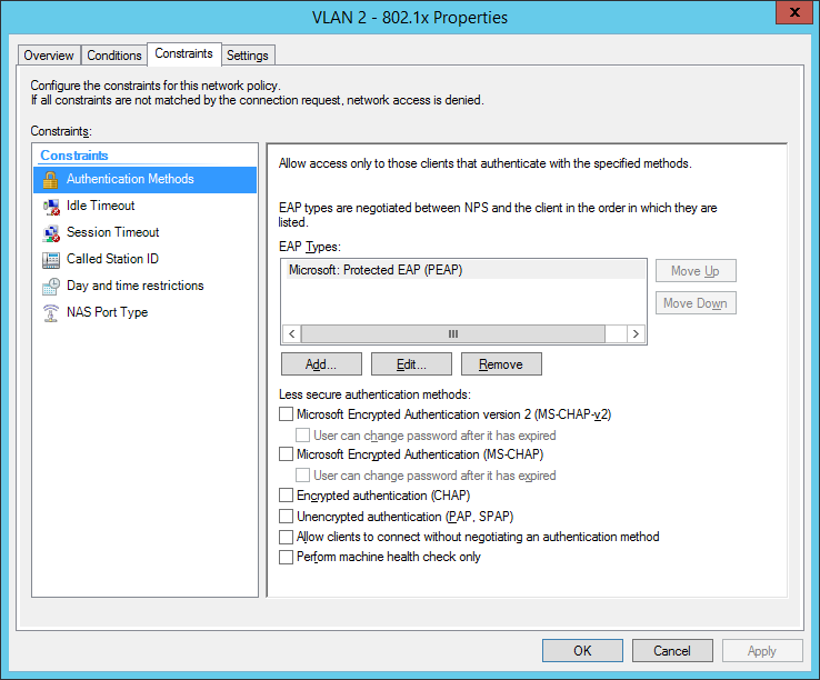
the next step is for our dynamic VLAN assignment. Dot1x devices are bound to VLAN 2:
the final dot1x configuration in the NPS:
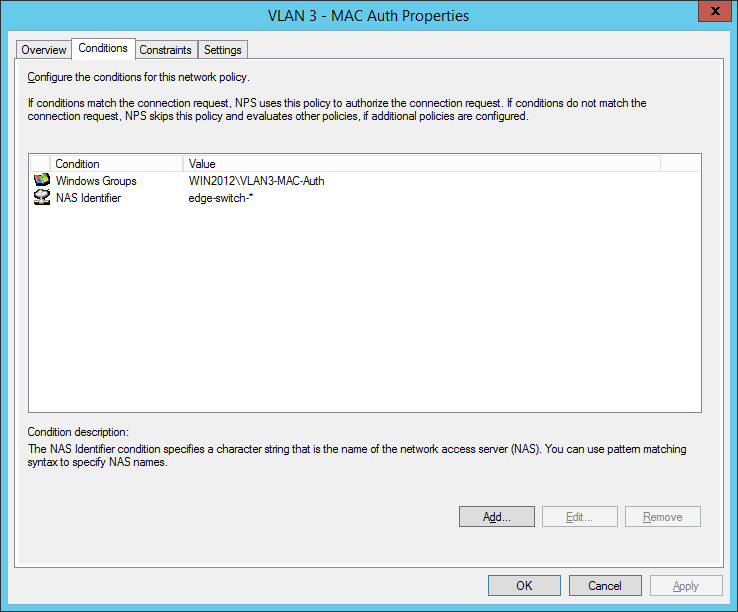
the second network policy is for the mac-based authentication:
Comware switches are sending MAC-Auth-requests via PAP (maybe you know how to change it to CHAP):
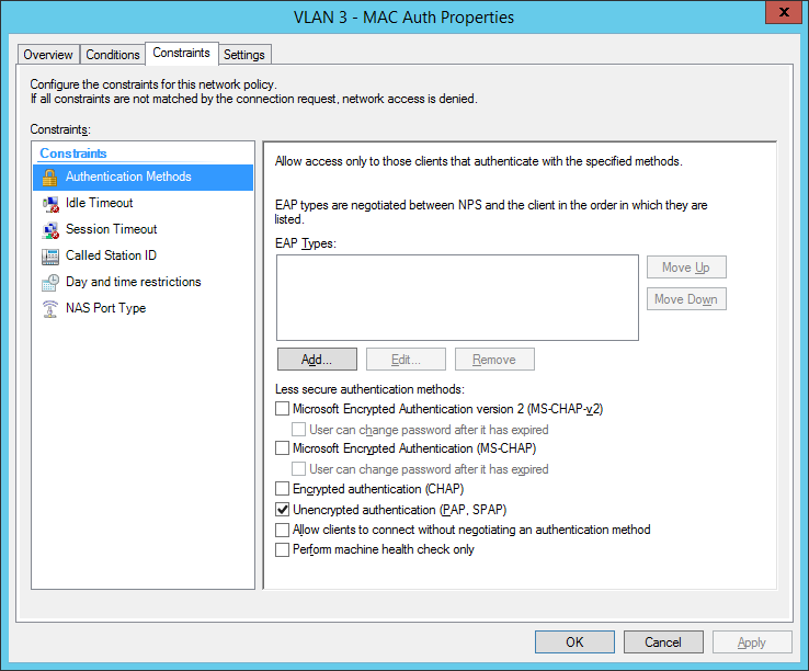
final MAC auth profile:
for now we have built up our authentication server. Now let’s go to the switch configuration. You have global configuration parameters and parameters for each interface. The best way is to use interface-range command to be safe at your configuration. Users who cant authenticate, will be forced to VLAN 999 (quarantine VLAN with no gateway). Here are the global parameters with explanations inline:
now we will configure the interfaces: Added 2 entries
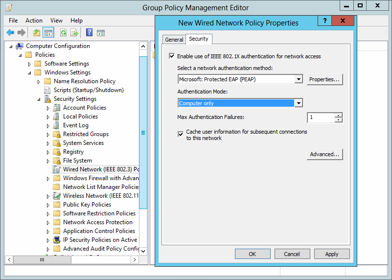
the last part is to configure all windows clients to send 802.1x auth data to the cable network. I’ve done this via a global group policy. You can find the settings under Computer Configuration / Policies / Windows Settings / Security Settings / Wired Network (IEEE 802.3) Policies:
So how does a working 802.1x-auth looks like?
%Jan 3 01:59:59:531 2013 edge-switch-01 DOT1X/6/DOT1X_LOGIN_SUCC: -IfName=GigabitEthernet1/0/10-MACAddr=0023-2415-42a3-AccessVLANID=1- AuthorizationVLANID=2 -Username= host/PC123.mycompany.local ; User passed 802.1X authentication and came online.
Successful Mac-Authentication of a printer:
%Jan 3 01:31:28:782 2013 de-pad-l19-edg01 MACA/6/MACA_LOGIN_SUCC: -IfName=GigabitEthernet1/0/9-MACAddr=0017-c82d-e9bf-AccessVLANID=1- AuthorizationVLANID=3 -Username= 0017c82de9bf -UsernameFormat=MAC address; User passed MAC authentication and came online.
I tried to draw a flow chart which shows the authentication process, I hope it’s ok for you :)
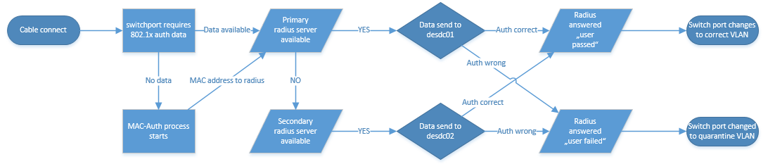
Do you have questions? Feel free to write them into the comments and I will try to answer.
Have a nice and sunny day!
/edit: If you can’t see success and failure events, follow this instruction: NPS / Radius Server is not logging
/edit 2018-05-14: I corrected the global and interface configuration, we had problems with the old configuration
12 Responses
Thanks for this, I need to setup dynamic VLAN assignment in the near future but for Juniper equipment.
This at least gives me a good starting point, thanks for the write up.
Many thanks for the perfect tutorial on How to use 802.1x/Mac-Auth and dynamic VLAN assignment. Many of us can take help from it. Really nice.
Nice write-up. This was a great starting point for configuring the base for dynamic polices. Thanks!
hi Mike, how ‘s about hybrid port with voice-vlan? does it work?
thanks Tung Duong
we had several problems with this config, currently we are investigating hyprid ports with “port security” command. I will update this post if we have prooved this version.
Can you tell me why I would do this over conventional static VLANs? What are the benefits radius dynamic VLANs?
we have customers which want to divide the network for clients, printers and “special devices”. So you have different group/radius-policies to directly place the devices in the right VLAN. Dynamic VLAN is only a bonus feature which you can use. Of course, you can use only the 802.1x and Mac authentication for security purpose.
I’m on the desktop side of things, so apologies if I use any incorrect terminology here.
Our Infrastructure team are looking at introducing 8021x in our schools. They have a test setup where all 8021x devices pick up a data centre VLAN regardless of which building they’re in – eg 10.100.50.
Each building WIRED has its own unique IP – SchoolA=10.120, SchoolB = 10.130 and so on.
I’ve asked if the 8021x setup can be where 8021x devices in SchoolA will get 10.120.50; SchoolB will get 10.130.50
This would allow us to easily determine which building LaptopA actually is, in the same way as we can with our wired desktops. It also saves on SCCM boundary issues causing applications/updates to be pulled over the WAN rather than the LAN.
It’s been suggested that this may not be possible. Could someone confirm this?
Thanks in advance.
Hello! This is of course possible!
My idea (with examples):
SchoolA=10.120 (Location: Chicago) SchoolB=10.130 (Location: Dallas)
So at Chicago you will have VLAN 333, every device is getting an IP address with 10.120.x.x. At Dallas every device in VLAN 333 is getting an IP address with 10.130.x.x. So the VLAN ID “333” is the same at every school but the DHCP scope and default gateway has it’s own address. So the device is getting the VLAN 333 at every location but another IP address. It’s very simple.
It’s not working if all schools are connected via Layer2 so VLAN333 can’t be a “standalone VLAN” at each geographical location.
Ask me any questions, I will try to help you.
- Pingback: 802.1x, MAC-Authentication and VLAN assignment at ProCurve/aruba Switches – Network Guy
- Pingback: Port Auth, Dynamic VLAN and Radius | samuelnotes
- Pingback: HPE Comware problem with mac authentication and printer - Network Guy
Leave a Reply Cancel reply
Click on the button to load the content from jetpack.wordpress.com.
Load content
This site uses Akismet to reduce spam. Learn how your comment data is processed .
Certificates

Post Categories
Post archives, recent posts.
- Sophos UTM 9.712-13 HA update problem 14. November 2022
- Sophos UTM 9.712-12 update released 24. August 2022
- Aruba OS Switch automatic vlan assignment for aruba APs 5. May 2022
- Sophos UTM 9.711-5 update released 22. April 2022
- Sophos UTM 9.710-1 update released 20. March 2022
Recent Comments
- Sophos Ssl Vpn Client Anmeldung - Login and Portal on Auto-Logon with Sophos SSL VPN Client (OpenVPN)
- Russell on Install Sophos UTM from USB Stick
- arno on Problems with incoming mails
- GigaTech IT on Installing Realtek Driver on ESXi 6.7
- Sophos User Portal Login Ssl Vpn - Online Login on Auto-Logon with Sophos SSL VPN Client (OpenVPN)
Franky’s Web Website from my friend Frank. News and Tricks about Microsoft products, primarly Exchange Server
Copyright by networkguy.de
Imprint · Privacy Policy
| > How RADIUS/802.1X authentication affects VLAN operation |
|
How RADIUS/802.1X authentication affects VLAN operation
Static vlan requirement:.
RADIUS authentication for an 802.1X client on a given port can include a (static) VLAN requirement. (Refer to the documentation provided with your RADIUS application.) The static VLAN to which a RADIUS server assigns a client must already exist on the switch. If it does not exist or is a dynamic VLAN (created by GVRP), authentication fails. Also, for the session to proceed, the port must be an untagged member of the required VLAN. If it is not, the switch temporarily reassigns the port as described below.
If the port used by the client is not configured as an untagged member of the required static VLAN:
When a client is authenticated on port “N”, if port “N” is not already configured as an untagged member of the static VLAN specified by the RADIUS server, then the switch temporarily assigns port “N” as an untagged member of the required VLAN (for the duration of the 802.1X session). At the same time, if port “N” is already configured as an untagged member of another VLAN, port “N” loses access to that other VLAN for the duration of the session. (This is because a port can be an untagged member of only one VLAN at a time.)
Using a RADIUS server to authenticate clients, you can provide port-level security protection from unauthorized network access for the following authentication methods:
802.1X: Port-based or client-based access control to open a port for client access after authenticating valid user credentials.
MAC address: Authenticates a device’s MAC address to grant access to the network
WebAgent: Authenticates clients for network access using a web page for user login.
| You can use 802.1X (port-based or client-based) authentication and either Web or MAC authentication at the same time on a port, with a maximum of 32 clients allowed on the port. (The default is one client.) Web authentication and MAC authentication are mutually exclusive on the same port. Also, you must disable LACP on ports configured for any of these authentication methods. | |
VLAN assignment on a port
Following client authentication, VLAN configurations on a port are managed as follows when you use 802.1X, MAC, or Web authentication:
The port resumes membership in any tagged VLANs for which it is already assigned in the switch configuration. Tagged VLAN membership allows a port to be a member of multiple VLANs simultaneously.
The port is temporarily assigned as a member of an untagged (static or dynamic) VLAN for use during the client session according to the following order of options.
The port joins the VLAN to which it has been assigned by a RADIUS server during client authentication.
If RADIUS authentication does not include assigning the port to a VLAN, then the switch assigns the port to the authorized-client VLAN configured for the authentication method.
If the port does not have an authorized-client VLAN configured, but is configured for membership in an untagged VLAN, the switch assigns the port to this untagged VLAN.
Operating notes
During client authentication, a port assigned to a VLAN by a RADIUS server or an authorized-client VLAN configuration is an untagged member of the VLAN for the duration of the authenticated session. This applies even if the port is also configured in the switch as a tagged member of the same VLAN. The following restrictions apply:
If the port is assigned as a member of an untagged static VLAN, the VLAN must already be configured on the switch. If the static VLAN configuration does not exist, the authentication fails. If the port is assigned as a member of an untagged dynamic VLAN that was learned through GVRP, the dynamic VLAN configuration must exist on the switch at the time of authentication and GVRP-learned dynamic VLANs for port-access authentication must be enabled.
If the dynamic VLAN does not exist or if you have not enabled the use of a dynamic VLAN for authentication sessions on the switch, the authentication fails.
To enable the use of a GVRP-learned (dynamic) VLAN as the untagged VLAN used in an authentication session, enter the aaa port-access gvrp-vlans command.
Enabling the use of dynamic VLANs in an authentication session offers the following benefits:
You avoid the need of having static VLANs pre-configured on the switch.
You can centralize the administration of user accounts (including user VLAN IDs) on a RADIUS server.
For information on how to enable the switch to dynamically create 802.1Q-compliant VLANs on links to other devices using the GARP VLAN Registration Protocol (GVRP), see “GVRP” in the Advanced Traffic Management Guide .
For an authentication session to proceed, a port must be an untagged member of the (static or dynamic) VLAN assigned by the RADIUS server (or an authorized-client VLAN configuration). The port temporarily drops any current untagged VLAN membership.
If the port is not already a member of the RADIUS-assigned (static or dynamic) untagged VLAN, the switch temporarily reassigns the port as an untagged member of the required VLAN (for the duration of the session). At the same time, if the port is already configured as an untagged member of a different VLAN, the port loses access to the other VLAN for the duration of the session. (A port can be an untagged member of only one VLAN at a time.)
When the authentication session ends, the switch removes the temporary untagged VLAN assignment and re-activates the temporarily disabled, untagged VLAN assignment.
If GVRP is already enabled on the switch, the temporary untagged (static or dynamic) VLAN created on the port for the authentication session is advertised as an existing VLAN.
If this temporary VLAN assignment causes the switch to disable a different untagged static or dynamic VLAN configured on the port (as described in the preceding bullet and in Example of untagged VLAN assignment in a RADIUS-based authentication session , the disabled VLAN assignment is not advertised. When the authentication session ends, the switch:
Removes the temporary untagged VLAN assignment and stops advertising it.
Re-activates and resumes advertising the temporarily disabled, untagged VLAN assignment.
If you modify a VLAN ID configuration on a port during an 802.1X, MAC, or Web authentication session, the changes do not take effect until the session ends.
When a switch port is configured with RADIUS-based authentication to accept multiple 802.1X and/or MAC or Web authentication client sessions, all authenticated clients must use the same port-based, untagged VLAN membership assigned for the earliest, currently active client session.
Therefore, on a port where one or more authenticated client sessions are already running, all such clients are on the same untagged VLAN.
(See MAC-based VLANs ).
If a RADIUS server subsequently authenticates a new client, but attempts to re-assign the port to a different, untagged VLAN than the one already in use for the previously existing, authenticated client sessions, the connection for the new client will fail.
Example of untagged VLAN assignment in a RADIUS-based authentication session
The following example shows how an untagged static VLAN is temporarily assigned to a port for use during an 802.1X authentication session. In the example, an 802.1X-aware client on port A2 has been authenticated by a RADIUS server for access to VLAN 22. However, port A2 is not configured as a member of VLAN 22 but as a member of untagged VLAN 33 as shown in Active VLAN configuration .
For example, suppose that a RADIUS-authenticated, 802.1X-aware client on port A2 requires access to VLAN 22, but VLAN 22 is configured for no access on port A2, and VLAN 33 is configured as untagged on port A2:
Active VLAN configuration

In Active VLAN configuration , if RADIUS authorizes an 802.1X client on port A2 with the requirement that the client use VLAN 22, then:
VLAN 22 becomes available as Untagged on port A2 for the duration of the session.
VLAN 33 becomes unavailable to port A2 for the duration of the session (because there can be only one untagged VLAN on any port).
To view the temporary VLAN assignment as a change in the active configuration, use the show vlan < vlan-id > command as shown in The active configuration for VLAN 22 temporarily changes for the 802.1X session where < vlan-id > is the (static or dynamic) VLAN used in the authenticated client session.
The active configuration for VLAN 22 temporarily changes for the 802.1X session

However, as shown in Active VLAN configuration , because VLAN 33 is configured as untagged on port A2 and because a port can be untagged on only one VLAN, port A2 loses access to VLAN 33 for the duration of the 802.1X session on VLAN 22.
You can verify the temporary loss of access to VLAN 33 by entering the show vlan 33 command as shown in The active configuration for VLAN 33 temporarily drops port 22 for the 802.1X session .
The active configuration for VLAN 33 temporarily drops port 22 for the 802.1X session

When the 802.1X client’s session on port A2 ends, the port removes the temporary untagged VLAN membership. The static VLAN (VLAN 33) that is “permanently” configured as untagged on the port becomes available again. Therefore, when the RADIUS-authenticated 802.1X session on port A2 ends, VLAN 22 access on port A2 also ends, and the untagged VLAN 33 access on port A2 is restored as shown in The active configuration for VLAN 33 restores port A2 after the 802.1X session ends .
The active configuration for VLAN 33 restores port A2 after the 802.1X session ends

Enabling the use of GVRP-learned dynamic VLANs in authentication sessions
aaa port-access gvrp-vlans Enables the use of dynamic VLANs (learned through GVRP) in the temporary untagged VLAN assigned by a RADIUS server on an authenticated port in an 802.1X, MAC, or Web authentication session. Enter the no form of this command to disable the use of GVRP-learned VLANs in an authentication session. For information on how to enable a switch to dynamically create 802.1Q-compliant VLANs, see “GVRP” in the Advanced Traffic Management Guide . NOTE: If a port is assigned as a member of an untagged dynamic VLAN, the dynamic VLAN configuration must exist at the time of authentication and GVRP for port-access authentication must be enabled on the switch. If the dynamic VLAN does not exist or if you have not enabled the use of a dynamic VLAN for authentication sessions on the switch, the authentication fails. After you enable dynamic VLAN assignment in an authentication session, it is recommended that you use the interface unknown-vlans command on a per-port basis to prevent denial-of-service attacks. The interface unknown-vlans command allows you to: Disable the port from sending advertisements of existing GVRP-created VLANs on the switch. Drop all GVRP advertisements received on the port. See “GVRP” in the Advanced Traffic Management Guide . If you disable the use of dynamic VLANs in an authentication session using the no aaa port-access gvrp-vlans command, client sessions that were authenticated with a dynamic VLAN continue and are not deauthenticated. (This behavior differs from how static VLAN assignment is handled in an authentication session. If you remove the configuration of the static VLAN used to create a temporary client session, the 802.1X, MAC, or Web authenticated client is deauthenticated.) However, if a RADIUS-configured dynamic VLAN used for an authentication session is deleted from the switch through normal GVRP operation (for example, if no GVRP advertisements for the VLAN are received on any switch port), authenticated clients using this VLAN are deauthenticated.
| Any port VLAN-ID changes you make on 802.1X-aware ports during an 802.1X-authenticated session do not take effect until the session ends. With GVRP enabled, a temporary, untagged static VLAN assignment created on a port by 802.1X authentication is advertised as an existing VLAN. If this temporary VLAN assignment causes the switch to disable a configured (untagged) static VLAN assignment on the port, then the disabled VLAN assignment is not advertised. When the 802.1X session ends, the switch: Eliminates and ceases to advertise the temporary VLAN assignment. Re-activates and resumes advertising the temporarily disabled VLAN assignment | |
|
|
|
|
| Displaying 802.1X configuration, statistics, and counters |
| Messages related to 802.1X operation |
Copyright © 2015 Hewlett-Packard Development Company, L.P.
You are using an outdated browser. Please upgrade your browser to improve your experience.
Your browser does not support JavaScript. Please turn it on for the best experience.
Configuration Guide on Dynamic VLAN with the VLAN Assignment function of RADIUS
OC200 , OC300 , Omada Software Controller , Omada Cloud-Based Controller
Recent updates may have expanded access to feature(s) discussed in this FAQ. Visit your product's support page, select the correct hardware version for your device and check either the Datasheet or the firmware section for the latest improvements added to your product.
With the VLAN Assignment feature of RADIUS, the Omada SDN solution can put clients authenticated by different accounts to the corresponding VLANs. In this way, clients will obtain IP addresses from different VLANs, and you don't have to create many SSIDs bound with different VLANs for wireless networks, or bind the PVIDs of the switch ports to specific VLANs for wired networks.
To achieve the above features, you will need the Omada SDN Controller, EAP for wireless assignment, JetStream Switch for wired assignment, and an external RADIUS server. In this article, we will share the configuration guide for below network topology.

Step 1. Set up the RADIUS server.
Here we run a FreeRADIUS ® server on a Linux server. For more information on installation and configuration, please refer to the official website: https://freeradius.org/
First, edit the “ clients.conf ” file, set the client IP address as “192.168.0.0/24” and the password as “tplink”.

Next, edit the “ users ” file, create two accounts “test10” and “test20” in VLAN10 and VLAN20, respectively.

You may also edit the “ eap.conf ” to modify the EAP type for WPA-Enterprise. After configuration, run the RADIUS server to listen for access requests.
Step 2. Create the RADIUS profile.
Go to Authentication --- RADIUS Profile, create a new profile bound with the RADIUS server, and check “Enable VLAN Assignment for Wireless Network” to assign VLANs for wireless clients.

Step 3. Create more VLAN for VLAN assignments.
Assuming all Omada devices have been adopted by the controller, go to Settings --- Wired Networks --- LAN, and create two interfaces with VLAN10 and VLAN20.

Step 4. VLAN assignment for wireless networks.
Go to Settings – Wireless Networks, and create a new SSID with WPA-Enterprise as below. For differences between WPA-Personal and WPA-Enterprise, please refer to FAQ500 .

When connecting your client to the SSID, you will be asked to choose the authentication type of WPA-Enterprise, and enter the account username and password. After successfully authenticating with account “test10”, the client will obtain an IP address from VLAN10, while with account “test20”, it will get that from VLAN20.
Step 5. VLAN assignment for wired networks.
Go to Authentication --- 802.1X and enable the feature, select Authentication Type as “Port Based”, enable “VLAN Assignment” and check the Ports to be authenticated according to your requirements.
Not to click the ports twice to enable MAB for them.

Then go to Wired Networks --- LAN --- Profile, create a new port profile, add VLAN10 and VLAN20 to untagged networks, and make sure the 802.1X Control mode is Auto.

Then Go to Devices, click your switch, go to Ports, check the authentication ports, and batch edit to change the port profile to the one created just now.

For 802.1X authentication, you may need to run TP-Link 802.1X Client Software (click here to download) for authentication. Please refer to FAQ787 and Step 3. For detailed guidance.
Is this faq useful?
Your feedback helps improve this site.
What’s your concern with this article?
- Dissatisfied with product
- Too Complicated
- Confusing Title
- Does not apply to me
We'd love to get your feedback, please let us know how we can improve this content.
We appreciate your feedback. Click here to contact TP-Link technical support.
Recommend Products

Omada Cloud-Based Controller

Omada Software Controller

Omada Hardware Controller
TP-Link Community
Still need help? Search for answers, ask questions, and get help from TP-Link experts and other users around the world.
Visit the Community >
From Russia?
Get products, events and services for your region.
We have updated our Policies. Read Privacy Policy and Terms of Use here. This website uses cookies to improve website navigation, analyze online activities and have the best possible user experience on our website. You can object to the use of cookies at any time. You can find more information in our privacy policy .
Basic Cookies
These cookies are necessary for the website to function and cannot be deactivated in your systems.
accepted_local_switcher, tp_privacy_base, tp_privacy_marketing, tp_smb-select-product_scence, tp_smb-select-product_scenceSimple, tp_smb-select-product_userChoice, tp_smb-select-product_userChoiceSimple, tp_smb-select-product_userInfo, tp_smb-select-product_userInfoSimple, tp_top-banner, tp_popup-bottom, tp_popup-center, tp_popup-right-middle, tp_popup-right-bottom, tp_productCategoryType
__livechat, __lc2_cid, __lc2_cst, __lc_cid, __lc_cst, CASID
id, VISITOR_INFO1_LIVE, LOGIN_INFO, SIDCC, SAPISID, APISID, SSID, SID, YSC, __Secure-1PSID, __Secure-1PAPISID, __Secure-1PSIDCC, __Secure-3PSID, __Secure-3PAPISID, __Secure-3PSIDCC, 1P_JAR, AEC, NID, OTZ
Analysis and Marketing Cookies
Analysis cookies enable us to analyze your activities on our website in order to improve and adapt the functionality of our website.
The marketing cookies can be set through our website by our advertising partners in order to create a profile of your interests and to show you relevant advertisements on other websites.
Google Analytics & Google Tag Manager
_gid, _ga_<container-id>, _ga, _gat_gtag_<container-id>
Google Ads & DoubleClick
test_cookie, _gcl_au
cebsp_, _ce.s, _ce.clock_data, _ce.clock_event, cebs
OptanonConsent, _sctr, _cs_s, _hjFirstSeen, _hjAbsoluteSessionInProgress, _hjSessionUser_14, _fbp, ajs_anonymous_id, _hjSessionUser_<hotjar-id>, _uetsid, _schn, _uetvid, NEXT_LOCALE, _hjSession_14, _hjid, _cs_c, _scid, _hjAbsoluteSessionInProgress, _cs_id, _gcl_au, _ga, _gid, _hjIncludedInPageviewSample, _hjSession_<hotjar-id>, _hjIncludedInSessionSample_<hotjar-id>
lidc, AnalyticsSyncHistory, UserMatchHistory, bcookie, li_sugr, ln_or
Stack Exchange Network
Stack Exchange network consists of 183 Q&A communities including Stack Overflow , the largest, most trusted online community for developers to learn, share their knowledge, and build their careers.
Q&A for work
Connect and share knowledge within a single location that is structured and easy to search.
802.1x authentication and dynamic VLAN assignment of VLAN tagged frames
I want to implement a Network Access Control ( NAC ) infrastructure in my LAN. My topology is something like:
PC -> ( Untagged Port - PVID 100 - Non 802.1x capable smart switch ) -> ( Hybrid port - 802.1x Dynamic VLAN capable managed switch ) -> PacketFence
So, PCs and other devices aren´t connected directly to the 802.1x Dynamic VLAN capable switch ( HP 1920G ) but to a smart switch ( TP-Link TL-1016DE ). This switch tag frames coming into the untagged port with VLAN ID 100 and send them tagged to the 1920.
My question is: a tagged frame could be subject of 802.1x authentication and dynamic VLAN assigment by the 1920? or that just work for untagged frames?
Thanks in advance
- network-access
- ieee-802.1x
- 1 You trust on trunk ports between switches. The 802.1X frames are link-only frames that should not get beyond the first switch. In all likelihood, having a switch between the hosts and the 802.1X port will prevent 802.1X from functioning. – Ron Maupin ♦ Commented Oct 18, 2016 at 20:01
Unfortunately, 802.1X uses link-local frames. An 802.1D compliant bridge (switch) does not forward these types of frames (multicast OUI 01:80:C2). You should not be able to do 802.1X authentication across an intervening bridge or switch, so what you propose should not be possible.
Basically, you need to run 802.1X on the access ports of the access switch. Switches should be configured to trust on switch-to-switch links.
- You are right about that a switch doesn´t forward 802.1x frames. – Manuel Lapeyre Commented Oct 19, 2016 at 16:55
- Just for your information, I found that Linux kernel 3.2+ bridge allows that: gremwell.com/linux_kernel_can_forward_802_1x – Manuel Lapeyre Commented Oct 19, 2016 at 16:57
- That is another way in which Linux isn't open standards compliant when it comes to networking. – Ron Maupin ♦ Commented Oct 19, 2016 at 18:04
Your Answer
Sign up or log in, post as a guest.
Required, but never shown
By clicking “Post Your Answer”, you agree to our terms of service and acknowledge you have read our privacy policy .
Not the answer you're looking for? Browse other questions tagged vlan switching network-access ieee-802.1x or ask your own question .
- Featured on Meta
- Upcoming initiatives on Stack Overflow and across the Stack Exchange network...
- We spent a sprint addressing your requests — here’s how it went
Hot Network Questions
- Is prescreening not detrimental for paid surveys?
- Is "double-lowercase-L" a ligature (Computer Modern Italic)?
- Big zeros in block diagonal matrix
- Are there countries where only voters affected by a given policy get to vote on it?
- Simplicial Generalization of Pythagoras
- 80's/90's anime about a mecha made out of bones
- Does physical reality exist without an observer?
- Time integration of first-order ODE with higher-order information
- Are there other proposed translations of "aelfheres" in Beowulf than a name?
- What's the shape of the Control Weather spell? (if any)
- Equivalence of first/second choice with naive probability - I don't buy it
- Translate Pandas groupby plus resample to Polars in Python
- These two Qatar flights with slightly different times and different flight number must actually be the same flight, right?
- Is it a security issue to expose PII on any publically accessible URL?
- Are you radical enough to solve this SURDOKU?
- How are GameManagers created in Unity?
- Best Way to Determine if a Table has a Long Running Transaction
- Shasta Daisy Next Bud
- Deriving |𝐶𝐶𝑍⟩ magic states from |𝐶𝐶𝐶𝑍⟩?
- Can a MicroSD card help speed up my Mini PC?
- Quantum: why linear combination of vectors (superposition) is described as "both at the same time"?
- Is a "single" cpu safer than multiple cores?
- Sci fi book that has a tunnel. Depending on where you go through wall, go to different planet
- Are any Population III stars red dwarfs?
Meraki Community
- Community Platform Help
- Contact Community Team
- Meraki Documentation
- Meraki DevNet Developer Hub
- Meraki System Status
- Technical Forums
802.1x - Dynamic VLAN assignment?
- Subscribe to RSS Feed
- Mark Topic as New
- Mark Topic as Read
- Float this Topic for Current User
- Printer Friendly Page

- Mark as New
- Report Inappropriate Content
- All forum topics
- Previous Topic

- New July 8: Points Contest: Week 1 Roundup
- July 1: Recognizing the June 2024 Members of the Month
- July 1: The annual points contest is BACK and better than ever!
- Interfaces 232
- Layer 2 250
- Layer 3 181
- Community guidelines
- Cisco privacy
- Khoros privacy
- Terms of service
| Internet-Draft | 6mops | July 2024 |
| Linkova & Buraglio | Expires 8 January 2025 | [Page] |
IPv6-Mostly Networks: Deployment and Operations Considerations
This document discusses a deployment scenario called "an IPv6-Mostly network", when IPv6-only and IPv4-enabled endpoints coexist on the same network (network segment, VLAN, SSID etc). 
Status of This Memo
This Internet-Draft is submitted in full conformance with the provisions of BCP 78 and BCP 79. 
Internet-Drafts are working documents of the Internet Engineering Task Force (IETF). Note that other groups may also distribute working documents as Internet-Drafts. The list of current Internet-Drafts is at https://datatracker.ietf.org/drafts/current/ . 
Internet-Drafts are draft documents valid for a maximum of six months and may be updated, replaced, or obsoleted by other documents at any time. It is inappropriate to use Internet-Drafts as reference material or to cite them other than as "work in progress." 
This Internet-Draft will expire on 8 January 2025. 
Copyright Notice
Copyright (c) 2024 IETF Trust and the persons identified as the document authors. All rights reserved. 
This document is subject to BCP 78 and the IETF Trust's Legal Provisions Relating to IETF Documents ( https://trustee.ietf.org/license-info ) in effect on the date of publication of this document. Please review these documents carefully, as they describe your rights and restrictions with respect to this document. Code Components extracted from this document must include Revised BSD License text as described in Section 4.e of the Trust Legal Provisions and are provided without warranty as described in the Revised BSD License. 
Table of Contents
1. introduction.
While most network operators initially deploy IPv6 alongside their existing IPv4 infrastructure, pure IPv6-only networks remain uncommon outside of the mobile carrier space. This dual-stack approach is seen as a necessary transition phase, allowing operators to gain experience with IPv6 while minimizing disruption. 
However, dual-stack networks do not address the core problem driving IPv6 adoption: IPv4 address exhaustion. They still require the same amount of IPv4 resources as IPv4-only networks. Even worse, this dual-stack approach has been demonstrated to be a long-term crutch, frequently masking problems that would otherwise be exposed and remedied as normal operational workflows. Many applications still rely on IPv4, creating a chicken-and-egg problem: IPv6-only networks seem impractical with so many incompatible applications, yet applications continue to rely on IPv4 because IPv6-only networks are rare. 
The less control a network operator has over devices and applications, the more difficult it is to break IPv4 dependencies and move to IPv6-only. This is particularly challenging in enterprise networks with legacy IPv4-dependent applications and public Wi-Fi networks where operators cannot guarantee device compatibility. 
To enable a gradual transition, operators need to identify which devices can function in IPv6-only mode and which cannot. Creating separate network segments for each type introduces complexity and scalability issues – a major hurdle to IPv6-only adoption. 
A more desirable approach is to deploy an "IPv6-mostly" network that provides IPv4 on demand. This allows IPv6-capable devices to remain IPv6-only while seamlessly supplying IPv4 to those that require it. An IPv6-mostly network allows Endpoints to operate at the highest level of their network stack evolution, on demand, while still allowing for legacy compatibility. 
This document explores the requirements, recommendations, and challenges associated with deploying IPv6-mostly networks in enterprise and public Wi-Fi environments. While the principles discussed may be applicable to other network types, this document's focus remains on these specific use cases. 
2. Requirements Language
The key words "MUST", "MUST NOT", "REQUIRED", "SHALL", "SHALL NOT", "SHOULD", "SHOULD NOT", "RECOMMENDED", "NOT RECOMMENDED", "MAY", and "OPTIONAL" in this document are to be interpreted as described in BCP 14 [ RFC2119 ] [ RFC8174 ] when, and only when, they appear in all capitals, as shown here. 
3. Terminology
This document reuses most of Terminology section from [ RFC8925 ] . 
Endpoint: A device connected to a network and considered a host From the operator's perspective. However, some endpoint can also extend the network to other physical or logical systems, thereby assuming routing functions. Examples include: 
Corporate laptop: While primarily a host, it might run virtual systems and route traffic to them, extending the network and acting as a router. 
Mobile phone with tethering enabled: Acts as a host on the Wi-Fi network, but also as a router for tethered devices, potentially without the operator's knowledge or consent. 
Network segment: a link (VLAN, a broadcast domain etc) where hosts share the same IP subnet. 
PREF64: (or NAT64 prefix): An IPv6 prefix used for IPv6 address synthesis and for network addresses and protocols translation from IPv6 clients to IPv4 servers, [ RFC6146 ] . 
4. Solution Overview
In a nutshell, an IPv6-mostly network is very much similar to a dual-stack one with two additional key elements: 
The network provides NAT64 ( [ RFC6146 ] ) functionality ([RFC6146]), enabling IPv6-only clients to communicate with IPv4-only destinations. 
The DHCPv4 infrastructure processing DHCPv4 Option 108 as per [ RFC8925 ] . 
Upon connecting to an IPv6-mostly network segment, an endpoint configures its IP stack based on its capabilities: 
IPv4-Only Endpoint: Acquires an IPv4 address through DHCPv4. 
Dual-Stack Endpoint (Not IPv6-Only Capable): Configures IPv6 addresses via Stateless Address Autoconfiguration (SLAAC) and, optionally, DHCPv6. Additionally, it obtains an IPv4 address via DHCPv4 or by other means. 
IPv6-only capable endpoint configures its IPv6 addresses and, while performing DHCPv4, includes option 108 ( [ RFC8925 ] ) into the Parameter Request List. The DHCP server returns the option and, as per [ RFC8925 ] , the endpoint forgoes requesting an IPv4 address, remaining in IPv6-only mode. 
An IPv6-mostly network segment can support a mix of IPv4-only, dual-stack, and IPv6-only devices. IPv6-only endpoints utilize the network-provided NAT64 along with DNS64 services to reach IPv4-only destinations. 
The following sections discussed the various solution elements in more details. 
4.1. IPv6-Only Capable Endpoints
The term "IPv6-only capable endpoint" lacks a strict technical definition. It broadly describes a device that can function without native IPv4 connectivity/IPv4 addresses, providing the same user experience. The most common way to achieve this is by implementing a customer-side translator (CLAT) as specified in 464XLAT ( [ RFC6877 ] ). Devices which support CLAT (such as mobile phones) are known to operate without issues in IPv6-only mode. In some cases, however, a network administrator may consider a device IPv6-only capable even without CLAT implementation. For example, if all applications run on the device have been tested and confirmed to operate in NAT64 envinronment without any IPv4 dependencies. 
4.2. IPv6-Only and IPv4-enabled Endpoints Coexistence
One effective way to restrict IPv4 addresses solely to devices that require them is to enable support for the IPv6-Only Preferred DHCPv4 option (Option 108, [ RFC8925 ] ) on the network's DHCP infrastructure. Most CLAT-enabled systems also support Option 108. By recognizing this option, the network can configure those devices as IPv6-only, allowing them to use CLAT for providing IPv4 address to the local endpoint's network stack. 
Certain devices, such as resource-constrained embedded systems, may operate in IPv6-only mode without CLAT if their communication is limited to IPv6-enabled destinations. Since these systems often lack Option 108 support, administrators may need alternative methods to prevent IPv4 address assignment. One approach is to block IPv4 traffic at the switchport level. This could involve: 
Static ACL: Applying a static filter with a "deny ip any any" rule. 
Dynamic ACL via RADIUS: If 802.1x authentication is in use, RADIUS can provide an ACL blocking all IPv4 traffic. 
Filtering the IPv4 ethertype (0x0800): Some hardware platforms may allow for low level filtering of ethertype 0x0800 preventing IPv4 from passing into or out of a given switchport. 
The ACL-based approach has some scalability implications and increases operational complexity, therefore it could only be recommended as a stopgap solution. 
4.3. Access to IPv4-only Destinations
4.3.1. nat64.
IPv6-only endpoints require NAT64 to access IPv4-only destinations. Quite often operators choose to combine NAT44 and NAT64 functions. However, if not all internal services are IPv6-enabled, then NAT64 might need to be performed closer to the clients. If IPv4-only internal destinations are using [ RFC1918 ] address space, then the operator MUST NOT use the well-known prefix 64:ff9b::/96 for NAT64 (see section 3.1 of [ RFC6052 ] ). 
4.3.2. 464XLAT
Enabling CLAT (Customer-side translator) on endpoints is essential for seamless operation of IPv4-only applications in IPv6-only environments. CLAT provides an [ RFC1918 ] address and IPv4 default route, ensuring functionality even without a native IPv4 address from the network. Without CLAT, IPv4-only applications would fail, negatively impacting user experience and increasing support overhead. 
Recommendations for Network Administrators controlling the endpoints: 
CLAT + DHCPv4 Option 108: If the network administrator can control endpoint configuration, CLAT SHOULD be enabled on endpoints sending DHCPv4 Option 108. This streamlines the transition. 
Option 108 Without CLAT MAY be enabled if the administrator is willing to identify and fixIPv4-only systems/applications, or if all applications are confirmed to work in IPv6-only mode. 
4.3.3. Signalling NAT64 Prefix to Hosts
Hosts running 464XLAT need to discover the PREF64 (the IPv6 prefix used by NAT64). The network administrator SHOULD configure the first-hop routers to include PREF64 information in Router Advertisements as per ( [ RFC8781 ] ) even if the network provides DNS64 (so hosts can use DNS64-based prefix discovery, [ RFC7050 ] ). This is required as hosts or individual applications might have custom DNS configuration (or even run a local DNS server) and ignore DNS64 information provided by the network, so they can not use [ RFC7050 ] method to detect PREF64. In the absense of PREF64 information in Router Advertisements such systems would not be able to run CLAT, which would cause connectivity issues for all IPv4-only applications running on the affected device. As such device wouldn't be able to use the network-provided DNS64, access to IPv4-only destination would be impacted as well. At the time of writing all major OSes supporting DHCPv4 option 108 and enabling CLAT automatically also support [ RFC8781 ] . Therefore providing PREF64 information in RAs can reliably mitigate the impact of custom DNS configuration on those systems. 
Receiving PREF64 information in RAs also speeds up the CLAT start up time, so an IPv4 address and default route become available for applications much faster. 
4.3.4. DNS vs DNS64
Traditionally, DNS64 (with NAT64) is used to enable IPv6-only endpoints to access IPv4-only destinations. However, using DNS64 has a number of drawbacks, such as: 
DNSSEC Incompatibility: DNS64 responses fail DNSSEC validation. 
Custom Resolvers: Endpoints or applications configured with custom resolvers or running recursive resolvers locally can not benefit from the DNS64 provided by the network. Such systems would need to rely on CLAT or local synthesis instead ( Section 7.3.8 discusses this scenario in more details). 
Additional requirements for application: to benefit from DNS64, applications need to be IPv6-enabled, use DNS (do not use IPv4 literals). Many applications do not satisfy those requirements and therefore fail if the endpoint does not have an IPv4 address/native IPv4 connectivity. Existence of such applications is the main reason why transition to IPv6-only must be incremental (via IPv6-mostly phase) and requires the vast majority of endpoints to support CLAT. 
Those concerns make DNS64 is suboptimal and undesirtable solution long-term. To eliminate the needs for DNS64, the network shall signal PREF64 to endpoints (see Section 4.3.3 ), and the endpoints need to use the obtained PREF64 for performing local synthesis and for CLAT. It should be noted that not every application can benefit from local synthesis performed by the operating system, as it would require the application to use DNS (not IP literals). Therefore DNS64 is only required to support the following cases: 
Systems and applications which perform local synthesis but do not support [ RFC8781 ] for prefix discovery, and can only discover the NAT64 prefix using [ RFC7050 ] . 
IPv6-only devices without CLAT (unless those endpoints are guaranteed never to need IPv4-only destinations, e.g. in case of a specialized network segment communicating solely with IPv6-capable destinations). 
5. Solution Benefits
5.1. benefits compared to dual-stack.
IPv6-Mostly networks offer significant advantages over traditional dual-stack models where endpoints have both IPv4 and IPv6 addresses: 
Drastically Reduced IPv4 Consumption: Dual-stack deployments don't solve the core problem of IPv4 address exhaustion. IPv6-Mostly allows to significantly reduce IPv4 consumption, as well as to reclaim IPv4 space. This reduction depends on endpoint capabilities (DHCPv4 Option 108 and CLAT support). In real-world scenarios, like conference Wi-Fi, 60-70% of endpoints may support IPv6-only operation, potentially allowing 2-4 times smaller IPv4 subnets. 
Simplified Operations: Managing dual-stack networks means running two network data planes simultaneously, increasing complexity, costs, and the potential for errors. IPv6-Mostly allows for the controlled phase out IPv4 from many endpoints, streamlining operations and improving overall network reliability at a measured and operator-controlled pace. 
Reduced Dependency on DHCPv4: As more devices operate seamlessly in IPv6-only mode, the criticality of DHCPv4 service diminishes significantly. This allows operators to scale down DHCPv4 infrastructure or operate it with less stringent SLOs, optimizing costs and resource allocation. 
5.2. Benefits Compared to a Dedicated IPv6-Only Network
Traditional IPv6-only adoption involves separate networks alongside dual-stack ones. IPv6-Mostly offers significant improvements: 
Enhanced Scalability: Separate IPv6-only networks double the number of SSIDs in wireless environments, causing channel congestion and degrading performance. IPv6-Mostly doesn't require additional SSIDs. Similarly, it allows IPv4 and IPv6-only devices to coexist on the same wired VLANs, eliminating the need of additional layer2 segments, VLAN IDs, and their respective layer3 configurations. 
Operational Simplicity: Managing one network segment for all clients (regardless of IPv4 needs) simplifies operations, improves user experience (no more confusing SSID choices), and reduces support tickets related to mismatched connections. Dynamic VLAN assignment becomes easier without device-specific IPv6 capability tracking. 
Optimized IPv4 Consumption: User-selected dual-stack networks often lead to unnecessary IPv4 use, as users often connect IPv6-only capable devices to a dual-stack network. IPv6-Mostly network allocates IPv4 addresses only when devices don't advertise IPv6-only capability (DHCPv4 Option 108). 
Improved Problem Visibility: User-selected fallback to dual-stack networks can mask issues with IPv6-only operation, hindering problem reporting and resolution. IPv6-Mostly forces users to work through any issues, improving identification and enabling fixes for smoother long-term transition. 
Flexible, Incremental Transition: IPv6-Mostly allows for gradual migration on a per-segment or even on per-device basis. Devices become IPv6-only only when deemed fully compatible with that mode. 
6. Incremental Rollout Considerations
Migrating endpoints to IPv6-only fundamentally changes network dynamics by removing the IPv4 safety net. This includes the masking effect of Happy Eyeballs. IPv6 connectivity issues become far more prominent, including those previously hidden within dual-stack environments. Operators should be prepared to discover and troubleshoot issues in both endpoints and network infrastructure, even if the dual-stack network appeared problem-free. 
Some rollout considerations are discussed in the following sections. 
6.1. Per-Device and Per-Subnet Incremental Rollout
Limited control over endpoint configuration necessitates a per-subnet rollout, incrementally enabling Option 108 processing in DHCP. If endpoint control exists, per-device rollout is possible (at least for OSes with configurable Option 108). Note that some OSes unconditionally enable Option 108 support, becoming IPv6-only the moment it's activated on the server side. The following approach is RECOMMENDED: 
DHCP Server-Side Activation: Enable Option 108 processing. Some OSes automatically switch to IPv6-only. Rollback at this stage affects the entire subnet. 
Controlled Endpoint Activation: Enable Option 108 on managed endpoints with per-device rollback possible. 
6.2. Rollback Approach
For quick rollback, the administrator SHOULD start with a minimal Option 108 value (300 seconds, Section 3.4 of [ RFC8925 ] ) and increase this value as the IPv6-mostly network proves reliable, reducing the likelihood of full-scale rollback. 
6.3. Opt-In and Opt-Out Modes
Before user-facing deployment, the administrator SHOULD consider a dedicated IPv6-mostly proof-of-concept network for early adopters. While this temporarily sacrifices some IPv6-mostly benefits ( Section 5.2 ), it provides valuable operational experience and early issue detection. 
Opt-In Phase: Invite tech-savvy early adopters to enable Option 108 and report issues. While response rates may be low, dedicated participants provide valuable troubleshooting data. 
Opt-Out Phase: Incrementally enable Option 108. Allow selective disabling for problematic endpoints. Disabling Option 108 SHOULD NOT be possible without a problem reports to ensure issue tracking and resolution. 
In some scenarios (see Section 7.3.1 ) the administrator MAY keep a dual-stack network as a last resort fallback mechanism but SHOULD prevent usesrs from connecting to it accidentially (e.g. it should be a hidden protected SSID). 
7. Operational Considerations
7.1. address assignment policy.
As outlined in Section 6.3 of [ RFC6877 ] , CLAT requires either a dedicated IPv6 prefix or, if unavailable, a dedicated IPv6 address. Currently (2024), all implementations use SLAAC for CLAT address acquisition. Therefore, to enable CLAT functionality within IPv6-mostly network segments, first-hop routers must advertise a Prefix Information Option (PIO) containing a globally routable SLAAC-suitable prefix with the 'Autonomous Address-Configuration' (A) flag set to zero. 
7.2. Extension Headers
Being an IPv6-specific concept, IPv6 extension headers are often neglected or even explictly prohibited by security policies in dual-stack networks. The issues caused by blockig extension headers might be masked by the presense of Happy Eyeballs but become highly visible when there is no IPv4 to fallback to. 
The network SHOULD permit at least the following extension headers: 
Fragment Header (Section 4.5 of [ RFC8200 ] ). Section 7.3.5 discusses the fragmentation in more details. 
ESP Header, which is used for IPSec traffic, such as VPN and Wi-Fi Calling. 
7.3. Typical Issues
IPv6-mostly networks expose hidden issues by removing the IPv4 safety net. While implementation bugs vary greatly and are beyond the scope of this document, this section focus on common problems caused by configuration, topology, or design choices. It's crucial to note that these issues likely pre-exist in dual-stack networks, but remain unnoticed due to IPv4 fallback. 
7.3.1. Hosts with Disabled or Disfunctional IPv6
Historically, tech support often advised disabling IPv6 as a quick workaround, leading to devices with disabled IPv6. Similarly, corporate IT may have disabled or filtered IPv6 under the assumption that it's not widely used. Such endpoints requesting Option 108 will fail to connect in an IPv6-mostly network, as they won't receive IPv4 addresses and IPv6 is disabled. 
Administrators controlling endpoints SHOULD ensure those endpoints have IPv6 enabled and operational before transitioning the network to IPv6-mostly mode. This includes verifying protocol enablement as well as validation of any central or discreetly managed host based firewalls that could potentially interfere with proper IPv6 function that may be masked by the presence of IPv4, and therefor exp[osed with its removal. 
7.3.2. Network Extension
IPv4's NAT44 allows endpoints to extend connectivity to downstream systems without upstream network awareness or permission. This creates challenges in IPv6-mostly deployments where endpoints lack IPv4 addresses: 
Solutions and trade-offs: 
Using DHCPv6-PD to allocate prefixes to endpoints ( [ I-D.ietf-v6ops-dhcp-pd-per-device ] ). Provides downstream systems with IPv6 addresses and native connectivity. 
Enabling the CLAT function on the endpoint. This scenario is similar to the Wireline Network Architecture described in Section 4.1 of [ RFC6877 ] . The downstream systems would receive IPv4 addresses and their IPv4 traffic would be translated to IPv6 by the endpoint. However this approach leads to the downstream systems using IPv4 only and not benefiting from end2end IPv6 connectivity. To enable IPv6 benefits, combine this with IPv6 Prefix Delegation as discussed above. 
Bridging and ND Proxy: The endpoint bridges IPv6 traffic and masks downstream devices behind its MAC address. This can lead to scalability issues ( Section 7.3.3 ) due to the single MAC being mapped to many IPv6 addresses. 
7.3.3. Multiple Addresses per Device
Unlike IPv4, where endpoints typically have a single IPv4 address per interface, IPv6 endpoints inherently use multiple addresses: 
Link-local address. 
Temporary address (common on mobile devices for privacy) 
Stable address (for long-term identification) 
CLAT address (in IPv6-mostly/IPv6-only networks) 
Endpoints with containers, namespaces, or ND proxy functions may have even more addresses. This poses challenges for network infrastructure devices (SAVI switches, wireless access points, etc.) that map MAC addresses to IPv6 addresses, often with limits to prevent resource exhaustion or DoS attacks. When the number of IPs per MAC limit is exceeded, infastructure devices behavior varies across implementations, leading to inconsistent connectivity loss and other unexpected behavior: while some systems drop new addresses, others delete older entries, causing previously functional addresses to lose connectivity. In all those cases Endpoints and applications don't receive explicit signalling about the address becoming unusable. 
While allocating prefixes to endpoints via DHCP-PD ( [ I-D.ietf-v6ops-dhcp-pd-per-device ] ) alows to eliminate the issue and corresponding scalability concerns, that solution migth not be supported by all endpoints. The network administrator SHOULD ensure that the deployed network infastructure devices allow sufficient number of IPv6 addresses to be mapped to a client's MAC and SHOULD monitor for events, indicating that the limit has been reached (such as syslog messages, etc). 
7.3.4. Host Mobility and Renumbering
Networks employing dynamic VLAN assignment (e.g., based on 802.1x or MAC-based authentication) can cause endpoints to move between VLANs and IPv6 subnets. As client operating systems do not always handle changes in link-layer state (e.g., VLAN changes) correctly, this mobility often leads to inconsistent IP stack behavior on operating systems, resulting in the persistence of old subnet addresses and potential connectivity issues due to incorrect source address selection. [ I-D.link-v6ops-gulla ] provides further analysis and potential solutions. 
7.3.5. Fragmentation
As the basic IPv6 header is 20 bytes longer than the IPv4 header, transating from IPv4 to IPv6 can result in packets exceeding the path MTU on the IPv6 side. In that case NAT64 creates IPv6 packets with the Fragment Header (see Section 4 of [ RFC6145 ] for more details. As per [ RFC6145 ] , by default the translator fragments IPv4 packets so that they fit in 1280-byte IPv6 packets. It means that all IPv4 packets larger than 1260 bytes are fragmented (or dropped if the DF bit is set). 
Administrators SHOULD maximize the path MTU on the IPv6 side (from the translator to IPv6-only hosts) to minimize fragmentation. NAT64 devices SHOULD be configured to use the actual path MTU on the IPv6 side when fragmenting IPv4 packets. 
Another common case of IPv6 fragmentation is the use of protocols like DNS and RADIUS, where the server response needs to be sent as a single UDP datagram. Network security policies MUST allow IPv6 fragments for permitted UDP traffic (e.g., DNS, RADIUS) where single-datagram responses are required. Allowing IPv6 fragments for permitted TCP traffic is RECOMMENDED unless the network infrastructure reliably performs TCP MSS clamping. 
7.3.6. Representing IPv6 Addresses by CLAT
Certain CLAT implementations face challenges when translating incoming IPv6 packets with native (non-synthesized) source addresses (e.g. ICMPv6 packets sent by intermediate hops on the path). This lack of standardized translation mechanisms can lead to: 
Incomplete Traceroute: Omission of IPv6-only hops between the endpoint and NAT64 translator, hindering troubleshooting. 
Path MTU Discovery Issues: Potential disruptions in the PMTU discovery process. 
[ I-D.equinox-intarea-icmpext-xlat-source ] proposes a solution for signalling the actual non-synthesized IPv6 source address while translating ICMPv6 error messages. 
7.3.7. IPv4-Dependencies in Network Admission Control
Certain layer 2 network devices (e.g., wireless access points, controllers) may enforce a policy where a host's network access is contingent upon successful DHCP IPv4 address assignment or tied to results of DHCP snooping. Consequently, hosts supporting Option 108 may experience network access denial or disconnection, as they are not assigned IPv4 addresses. 
7.3.8. Custom DNS Configuration on Endpoints
In IPv6-mostly networks without PREF64 in RAs, hosts rely on DNS64 ( [ RFC7050 ] to discover the NAT64 prefix for CLAT operation. [ RFC8880 ] requires that queries for AAAA resource records of "ipv4only.arpa." MUST be sent to the recursive resolvers provided by the network, not to the resolvers configured manually, local recursive resolvers etc. However some implementations do not comply with [ RFC8880 ] and, when configured with custom DNS resolvers (e.g., public or corporate DNS) may bypass the network-provided DNS64, preventing NAT64 prefix discovery and hindering CLAT functionality. 
Where feasible, administrators SHOULD include PREF64 in RAs within IPv6-mostly networks to minimize reliance on DNS64. Administrators need to be aware of the potential for CLAT failures when endpoints use custom resolvers in environments lacking PREF64. 
8. Security Considerations
The proposed deployment scenario inherits security considerations of IPv6 (see [ RFC9099 ] ). As IPv6-only device can not fall back to IPv4 if IPv6 connectivity is not available or impacted by a malicious actor. Therefore any attack affecting IPv6 connectivity would have much more drastic outcome, comparing to dual-stack networks. 
By signalling a rogue NAT64 prefix to a host, a malicious actor can: 
cause a DoS attack, if the network does not provide NAT64 functions (for that prefix or at all); 
implement MitM attack by intercepting traffic to the rogue prefix. 
To countermeasure this attack vector, the network administrators SHOULD configure the first-hop routers to include PREF64 information in Router Advertisements as per [ RFC8781 ] and ensure that layer 2 security measures such as RA-Guard ( [ RFC6105 ] ) are in place. Section 7 of [ RFC8781 ] discusses this topic in more details. Additionally, [ I-D.link-v6ops-claton ] discusses security implications of enabling CLAT if native IPv4 connectivity is available and recommends disabling CLAT in that case. 
Security considerations of using DHCP Option 108 are documented in Section 6 of [ RFC8925 ] . 
9. Privacy Considerations
This document does not introduce any privacy considerations. 
10. IANA Considerations
This memo does not introduce any requests to IANA. 
11. References
11.1. normative references, 11.2. informative references, acknowledgements.
Thanks to Ondrej Caletka, Brian Carpenter, Stuart Cheshire, Lorenzo Colitti, Jordi Palet, Michael Richardson, Matsuzaki Yoshinobu for the discussions, the feedback, and all contribution. 
Authors' Addresses
- Skip to content
- Skip to search
- Skip to footer
Configure Dynamic VLAN Assignment with WLCs Based on ISE to Active Directory Group Map
Available Languages
Download options.
- PDF (2.5 MB) View with Adobe Reader on a variety of devices
- ePub (2.7 MB) View in various apps on iPhone, iPad, Android, Sony Reader, or Windows Phone
- Mobi (Kindle) (2.4 MB) View on Kindle device or Kindle app on multiple devices
Bias-Free Language
The documentation set for this product strives to use bias-free language. For the purposes of this documentation set, bias-free is defined as language that does not imply discrimination based on age, disability, gender, racial identity, ethnic identity, sexual orientation, socioeconomic status, and intersectionality. Exceptions may be present in the documentation due to language that is hardcoded in the user interfaces of the product software, language used based on RFP documentation, or language that is used by a referenced third-party product. Learn more about how Cisco is using Inclusive Language.
Introduction
This document describes the concept of dynamic VLAN assignment.
Prerequisites
The document describes how to configure the wireless LAN controller (WLC) and Identity Services Engine (ISE) server in order to assign wireless LAN (WLAN) clients into a specific VLAN dynamically.
Requirements
Cisco recommends that you have knowledge of these topics:
Basic knowledge of Wireless LAN Controllers (WLCs) and Lightweight Access Points (LAPs)
Functional knowledge of an Authentication, Authorization, and Accounting (AAA) server such as an ISE
- Thorough knowledge of wireless networks and wireless security issues
- Functional and configurable knowledge of dynamic VLAN assignment
- Basic understanding of Microsoft Windows AD services, as well as a domain controller and DNS concepts
- Have basic knowledge of Control And Provisioning of Access Point protocol (CAPWAP)
Components Used
The information in this document is based on these software and hardware versions:
Cisco 5520 Series WLC that runs firmware release 8.8.111.0
Cisco 4800 Series AP
Native Windows supplicant and Anyconnect NAM
Cisco Secure ISE version 2.3.0.298
Microsoft Windows 2016 Server configured as a domain controller
Cisco 3560-CX Series Switch that runs version 15.2(4)E1
The information in this document was created from the devices in a specific lab environment. All of the devices used in this document started with a cleared (default) configuration. If your network is live, ensure that you understand the potential impact of any command.
Conventions
Refer to Cisco Technical Tips Conventions for more information on document conventions.
Dynamic VLAN Assignment with RADIUS Server
In most WLAN systems, each WLAN has a static policy that applies to all clients associated with a Service Set Identifier (SSID), or WLAN in the controller terminology. Although powerful, this method has limitations because it requires clients to associate with different SSIDs in order to inherit different QoS and security policies.
Cisco WLAN solution addresses that limitation by the support of identity networking. This allows the network to advertise a single SSID but allows specific users to inherit different QoS, VLAN attributes, and/or security policies based on the user credential.
Dynamic VLAN assignment is one such feature that places a wireless user into a specific VLAN based on the credentials supplied by the user. This task to assign users to a specific VLAN is handled by a RADIUS authentication server, such as Cisco ISE. This can be used, for example, in order to allow the wireless host to remain on the same VLAN as it moves within a campus network.
The Cisco ISE server authenticates wireless users against one of several possible databases, which includes its internal database. For example:
- Internal DB
Active Directory
Generic Lightweight Directory Access Protocol (LDAP)
Open Database Connectivity (ODBC)-compliant relational databases
Rivest, Shamir, and Adelman (RSA) SecurID token servers
RADIUS-compliant token servers
Cisco ISE Authentication Protocols and Supported External Identity Sources list the various authentication protocols supported by ISE internal and external databases.
This document focuses on authenticating wireless users that use Windows Active Directory external database.
After successful authentication, ISE retrieves the group information of that user from the Windows database and associates the user to the respective authorization profile.
When a client attempts to associate with a LAP registered with a controller, the LAP passes the credentials of the user to the WLC with the help of the respective EAP method.
WLC sends those credentials to ISE with the use of RADIUS protocol (encapsulating the EAP) and ISE passes the credentials of users to AD for validation with the help of the KERBEROS protocol.
AD validates the user credentials and upon successful authentication, informs the ISE.
Once the authentication is successful, the ISE server passes certain Internet Engineering Task Force (IETF) attributes to WLC. These RADIUS attributes decide the VLAN ID that must be assigned to the wireless client. The SSID (WLAN, in terms of WLC) of the client does not matter because the user is always assigned to this predetermined VLAN ID.
The RADIUS user attributes used for the VLAN ID assignment are:
IETF 64 (Tunnel Type) — Set this to VLAN
IETF 65 (Tunnel Medium Type) — Set this to 802
IETF 81 (Tunnel Private Group ID) — Set this to VLAN ID
The VLAN ID is 12 bits and takes a value between 1 and 4094, inclusive. Because the Tunnel-Private- Group-ID is of type string, as defined in RFC2868 for use with IEEE 802.1X, the VLAN ID integer value is encoded as a string. When these tunnel attributes are sent, it is necessary to fill in the Tag field.
As noted in RFC 2868 , section 3.1: the Tag field is one octet in length and is intended to provide a means of grouping attributes in the same packet which refer to the same tunnel. Valid values for this field are 0x01 through 0x1F, inclusive. If the Tag field is unused, it must be zero (0x00). Refer to RFC 2868 for more information on all RADIUS attributes.
This section provides the information needed to configure the described features in the document.
Network Diagram

Configurations
These are the configuration details of the components used in this diagram:
The IP address of the ISE (RADIUS) server is 10.48.39.128.
The Management and AP-manager Interface address of the WLC is 10.48.71.20.
DHCP server resides in the LAN network and is configured for respective client pools; it is not shown in the diagram.
VLAN1477 and VLAN1478 are used throughout this configuration. Users from the Marketing department are configured in order to be placed into the VLAN1477 and users from the HR department are configured in order to be placed into VLAN1478 by the RADIUS server when both users connect to the same SSID ― office_hq .
VLAN1477: 192.168.77.0/24. Gateway: 192.168.77.1 VLAN1478: 192.168.78.0/24. Gateway: 192.168.78.1
This document uses 802.1x with PEAP-mschapv2 as the security mechanism.
Note : Cisco recommends that you use advanced authentication methods, such as EAP-FAST and EAP-TLS authentication, in order to secure the WLAN.
These assumptions are made before you perform this configuration:
The LAP is already registered with the WLC
The DHCP server is assigned a DHCP scope
- Layer 3 connectivity exists between all devices in the network
The document discusses the configuration required on the wireless side and assumes that the wired network is in place
- Respective users and groups are configured on AD
In order to accomplish dynamic VLAN assignment with WLCs based on ISE to AD group mapping, these steps must be performed:
- ISE to AD integration and configuration of authentication and authorization policies for users on ISE.
- WLC configuration in order to support dot1x authentication and AAA override for SSID 'office_hq'.
- End client supplicant configuration.
ISE to AD Integration and Configuration of Authentication and Authorization Policies for Users on ISE
- Login to the ISE Web UI interface using an admin account.

WLC Configuration to Support dot1x Authentication and AAA Override for SSID 'office_hq'

Use the Windows 10 native supplicant and Anyconnect NAM in order to test connections.
Since you are using EAP-PEAP authentication and ISE is using a Self-Signed Certificate (SSC), you must agree to a certificate warning or disable certificate validation. In a corporate environment, you must use a signed and trusted certificate on ISE and ensure that the end-user devices have the appropriate root certificate installed under the Trusted CA list.
Test connection with Windows 10 and native supplicant:

- From the WLC CLI , the client status can be checked with the show client dertails <mac-address> : show client detail f4:8c:50:62:14:6b Client MAC Address............................... f4:8c:50:62:14:6b Client Username ................................. Bob Client Webauth Username ......................... N/A Hostname: ....................................... Device Type: .................................... Intel-Device AP MAC Address................................... 70:69:5a:51:4e:c0 AP Name.......................................... AP4C77.6D9E.6162 AP radio slot Id................................. 1 Client State..................................... Associated User Authenticated by ........................... RADIUS Server Client User Group................................ Bob Client NAC OOB State............................. Access Wireless LAN Id.................................. 3 Wireless LAN Network Name (SSID)................. office_hq Wireless LAN Profile Name........................ office_hq Hotspot (802.11u)................................ Not Supported Connected For ................................... 242 secs BSSID............................................ 70:69:5a:51:4e:cd Channel.......................................... 36 IP Address....................................... 192.168.78.36 Gateway Address.................................. 192.168.78.1 Netmask.......................................... 255.255.255.0 ... Policy Manager State............................. RUN ... EAP Type......................................... PEAP Interface........................................ vlan1478 VLAN............................................. 1478 Quarantine VLAN.................................. 0 Access VLAN...................................... 1478
Test connection with Windows 10 and Anyconnect NAM:

- From the WLC CLI , the client status can be checked with the show client dertails <mac-address> : Client MAC Address............................... f4:8c:50:62:14:6b Client Username ................................. Alice Client Webauth Username ......................... N/A Hostname: ....................................... Device Type: .................................... Intel-Device AP MAC Address................................... 70:69:5a:51:4e:c0 AP Name.......................................... AP4C77.6D9E.6162 AP radio slot Id................................. 1 Client State..................................... Associated User Authenticated by ........................... RADIUS Server Client User Group................................ Alice Client NAC OOB State............................. Access Wireless LAN Id.................................. 3 Wireless LAN Network Name (SSID)................. office_hq Wireless LAN Profile Name........................ office_hq Hotspot (802.11u)................................ Not Supported Connected For ................................... 765 secs BSSID............................................ 70:69:5a:51:4e:cd Channel.......................................... 36 IP Address....................................... 192.168.77.32 Gateway Address.................................. 192.168.77.1 Netmask.......................................... 255.255.255.0 ... Policy Manager State............................. RUN ... Policy Type...................................... WPA2 Authentication Key Management.................... 802.1x Encryption Cipher................................ CCMP-128 (AES) Protected Management Frame ...................... No Management Frame Protection...................... No EAP Type......................................... PEAP Interface........................................ vlan1477 VLAN............................................. 1477
Troubleshoot
- Use the test aaa radius username <user> password <password> wlan-id <id> in order to test the RADIUS connection between WLC and ISE and the test aaa show radius in order to show the results. test aaa radius username Alice password <removed> wlan-id 2 Radius Test Request Wlan-id........................................ 2 ApGroup Name................................... none Attributes Values ---------- ------ User-Name Alice Called-Station-Id 00-00-00-00-00-00:AndroidAP Calling-Station-Id 00-11-22-33-44-55 Nas-Port 0x00000001 (1) Nas-Ip-Address 10.48.71.20 NAS-Identifier 0x6e6f (28271) Airespace / WLAN-Identifier 0x00000002 (2) User-Password cisco!123 Service-Type 0x00000008 (8) Framed-MTU 0x00000514 (1300) Nas-Port-Type 0x00000013 (19) Cisco / Audit-Session-Id 1447300a0000003041d5665c Acct-Session-Id 5c66d541/00:11:22:33:44:55/743 test radius auth request successfully sent. Execute 'test aaa show radius' for response (Cisco Controller) >test aaa show radius Radius Test Request Wlan-id........................................ 2 ApGroup Name................................... none Radius Test Response Radius Server Retry Status ------------- ----- ------ 10.48.39.128 1 Success Authentication Response: Result Code: Success Attributes Values ---------- ------ User-Name Alice State ReauthSession:1447300a0000003041d5665c Class CACS:1447300a0000003041d5665c:rmanchur-ise/339603379/59 Tunnel-Type 0x0000000d (13) Tunnel-Medium-Type 0x00000006 (6) Tunnel-Group-Id 0x000005c5 (1477) (Cisco Controller) >
- Use the debug client <mac-address> in order to troubleshoot wireless client connectivity issues.
Note : Use this command only with the debug mac addr in order to limit the output based on the MAC address for which debugging is done.
- Refer to ISE live logs and session logs in order to identify problems authentication failures and AD communication issues.
Revision History
| Revision | Publish Date | Comments |
|---|
Contributed by Cisco Engineers
- Roman Manchur Cisco TAC Engineer
Was this Document Helpful?

Contact Cisco
- (Requires a Cisco Service Contract )
This Document Applies to These Products
- Identity Services Engine
- Wireless LAN Controller Software
- Wireless, LAN (WLAN)
IMAGES
VIDEO
COMMENTS
Restrictions for IEEE 802.1X VLAN Assignment. The IEEE 802.1X VLAN Assignment feature is available only on a switch port. The device port is always assigned to the configured access VLAN when any of the following conditions occurs: No VLAN is supplied by the RADIUS server. The VLAN information from the RADIUS server is not valid.
IEEE 802.1X Authentication and Dynamic VLAN Assignment with NPS Radius Server is an important element to networking in the real world. User location cannot be predicted as they may be at and out of a desk and up and about should they need to do so. ... Open Lounge with IEEE 802.1X Authentication with Dynamic VLAN for all users to function as if ...
The 802.1x protocol is used for network access control. For devices like printers, cameras, etc. we will use mac-authentication as a fallback. We will also use dynamic VLAN assignment for the connected ports. Our radius server will be Microsoft NPS. You can activate this role on the Windows server:
Dynamic VLAN assignment is one such feature that places a wireless user into a specific VLAN based on the credentials supplied by the user. The task to assign users to a specific VLAN is handled by a RADIUS authentication server, such as Cisco ISE. ... as defined in RFC2868 for use with IEEE 802.1X, the VLAN ID integer value is encoded as a ...
When configured on the switch and the RADIUS server, 802.1x authentication with VLAN assignment has these characteristics: If no VLAN is supplied by the RADIUS server or if 802.1x authentication is disabled, the port is configured in its access VLAN after successful authentication. ... If you try to enable 802.1x authentication on a dynamic ...
Syntax: Enables the use of dynamic VLANs (learned through GVRP) in the temporary untagged VLAN assigned by a RADIUS server on an authenticated port in an 802.1X, MAC, or Web authentication session. Enter the no form of this command to disable the use of GVRP-learned VLANs in an authentication session.
FreeRadius defines the users in a file called users. The RADIUS administrator needs to edit the "users" file to add in approved users. In the users file you can specify the VLAN memberships for users using EAP authentication, by using the following format: mary Auth-Type := EAP, User-Password == "moretest". Reply-Message = "Hello, %u",
Learn how to assign VLANs dynamically with RADIUS to Unleashed access points.For more information on this topic and many others, check out the Ruckus Support...
08-30-2019 10:30 AM. You can do dynamic VLAN assignment using ISE. Assuming you are doing 802.1x user authentication, you could have an authorization rule that matches on AD group membership to HR and if matches, then assign VLAN X. If in Sales AD group, then assign VLAN Y.
Dynamic assignment of the VLAN for the Voice domain requires an additional attribute, device-traffic-class=voice, to be included in the Access-Accept message from the RADIUS server. ... (VLANs) 802.1X Control Direction (Wake-on-LAN support)
The VLAN assignment feature allows you to restrict users to a specific VLAN. For example, you could put guest users in a VLAN with limited access to the network. 802.1x authenticated ports are assigned to a VLAN based on the username of the host that is connected to the port. This feature works with the RADIUS server that has a database of ...
The IEEE 802.1X VLAN Assignment feature is automatically enabled when IEEE 802.1X authentication is configured for an access port, which allows the RADIUS server to send a VLAN assignment to the device port. This assignment configures the device port so that network access can be limited for certain users.
Solved: 802.1X NPS Dynamic VLAN Assignment - Cisco Community. Solved: Hi Everyone, We're trying to configure a port-based authentication wherein user's successful login lands it on their assigned vlan. Please refer to the diagram. We've successfully done this over our wireless network, but the connection to.
It may be necessary to perform dynamic VLAN assignment on a per computer or per user basis. This can be done on your wired network via 802.1x authentication (RADIUS). In order to do so, the following RADIUS attributes must be configured and passed in the RADIUS Access-Accept message from the RADIUS server.
This article describes how to configure Omada SDN Controller and the RADIUS server to enable dynamic VLAN for both wired and wireless networks. ... VLAN assignment for wired networks. Go to Authentication --- 802.1X and enable the feature, select Authentication Type as "Port Based", enable "VLAN Assignment" and check the Ports to be ...
802.1x authentication and dynamic VLAN assignment of VLAN tagged frames. Ask Question Asked 7 years, 8 months ago. Modified 7 years, 8 ... ( Untagged Port - PVID 100 - Non 802.1x capable smart switch ) -> ( Hybrid port - 802.1x Dynamic VLAN capable managed switch ) -> PacketFence. So, PCs and other devices aren´t connected directly to the 802 ...
The IEEE 802.1X authentication with VLAN assignment feature is not supported on trunk ports, dynamic ports, or with dynamic-access port assignment through a VLAN Membership Policy Server (VMPS). If the multihost mode is enabled on an IEEE 802.1X port, all hosts are placed in the same VLAN (specified by the RADIUS server) as the first ...
Dynamic VLAN Assignment In lieu of CoA, MS switches can still dynamically assign a VLAN to a device by assigned the VLAN passed in the Tunnel-Pvt-Group-ID attribute. It may be necessary to perform dynamic VLAN assignment on a per computer or per user basis. This can be done on your wired network via 802.1x authentication (RADIUS).
You'll want to build an access policy that uses RADIUS and 802.1x. For all the other configurables, have a look at the doc @ww provided and make a call on what suites your environment best.. As for the auth based on device certificate and MAC address, those policies are configured on the RADIUS server as it will be performing the checks.
We've deployed Cisco ISE in our DC and we planned to control 802.1x wireless access from branch sites. We've already configured VPN tunnel between DC and Branches. We would like to configure Dynamic VLAN assignment to the client PCs on branch sites, i.e., we've only one SSID and users from different user groups will be assigned to ...
The 802.1x authentication with VLAN assignment feature is not supported on trunk ports, dynamic ports, or with dynamic-access port assignment through a VLAN Membership Policy Server (VMPS). To configure VLAN assignment you need to perform these tasks:
Dynamic VLAN assignment is one such feature that places a wireless user into a specific VLAN based on the credentials supplied by the user. ... 1 and 4094, inclusive. Because the Tunnel-Private-Group-ID is of type string, as defined in RFC2868 for use with IEEE 802.1X, the VLAN ID integer value is encoded as a string. When these tunnel ...
Dynamic ACL via RADIUS: If 802.1x authentication is in use, RADIUS can provide an ACL blocking all IPv4 traffic. ... Networks employing dynamic VLAN assignment (e.g., based on 802.1x or MAC-based authentication) can cause endpoints to move between VLANs and IPv6 subnets. As client operating systems do not always handle changes in link-layer ...
Dynamic VLAN assignment is one such feature that places a wireless user into a specific VLAN based on the credentials supplied by the user. This task to assign users to a specific VLAN is handled by a RADIUS authentication server, such as Cisco ISE. ... This document uses 802.1x with PEAP-mschapv2 as the security mechanism. Note: Cisco ...
802.1X Authentication Server Timeout . DHCP Discover Timeout. ... users can assign VLAN name as guest which should not be allowed as it is reserved for internal use. CNX-63632. ... A user cannot create a local object by editing the server IP of a shared object for NTP and dynamic DNS over HTTP. CNX-77293. A user cannot update the description of ...