RS232 Pinout and Specifications
Table of Contents:

What is RS232 Serial Communication Protocol?
- ♦ RS232 Standart Limitations
- ♦ DB25 connectors
- ♦ 9 pin RS-232 pinout
RS-232 signals
Rs-232 cables specifications, rs-232 data flow diagram, relationship between rs232 and other standards.
RS-232 is a standard that was introduced in the early 60s for serial data transmission and still widely in use mainly because it’s multipurpose, easy to operate and maintain, accessible, and widely supported. It defines not only electrical signal characteristics, such as signal transmission rate, voltage levels, cable length, timing and short-circuit behavior, but many other things as well, including interface’s mechanical characteristics, connectors, and pinouts.
According to RS-232 standard, all the data is transmitted in a time-series of bits. For PC, the most common configuration is asynchronous link sending 7-bit or 8-bit packets. However, this standard supports synchronous transmission too.

With all its merits, RS-232 has some serious limitations in range and data throughput performance, so its main scope of application is industrial gear, networking, and lab equipment.
Main specifications for RS-232
Operation mode: single-ended Max. cable length: 15.24 meters (50 ft) Max. data throughput: 20 kbps Max. driver output voltage: +/-25V Max. slew rate: 30V/uS Max. driver current in High Z state: +/-6mA @ +/-2v (power off) Driver load impedance: 3000-7000 Ohms Driver output signal level: +/-5V to +/-15V (loaded) or +/-25V (unloaded) Receiver input resistance: 3000-7000 Ohms Receiver input voltage range: +/-15V Receiver input sensitivity: +/-3V Total Number of Drivers and Receivers on One Line: 1 driver and 1 receiver
RS232 Standart Limitations
What are the known issues with the RS-232 serial port? Using the standard COM port comes with a bunch of limitations that you have to deal with. Here are the obvious limitations of the standard:
- Increased consumption of power due to large voltage swing is a huge complication for the power supply design.
- A lot of devices don’t use the handshake lines for flow control thereby making RS-232 unreliable.
- Although the multi-drop connection issue has been addressed with more reliable alternatives, it still doesn’t compensate for the compatibility and speed limitations of RS232 port.
- The need for a null modem or crossover cable whenever connecting a peripheral to a computer.
- RS-232 doesn’t solve the problem presented by single-ended signaling.
RS-232 connectors
An RS-232 device is either as a Circuit-terminating Equipment (DCE) or as a Data Terminal Equipment (DTE) depending on which wires are used to send and receive each signal.

In accordance with RS-232 standard, DCE is meant for female connectors, and DTE is for male connectors. However, there are devices with all sorts of connector gender/pin definitions combinations. For example, a terminal that has onboard female connectors to come with a cable that has a male connector at each end fully meets the RS-232 standard.
Up to revision C, the standard recommends using D-subminiature 25-pin connector, though it’s mandatory as of revision D only. That's because the vast majority of devices don’t really need all those standard-specified 20 signals, and RS-232 9-pin connections are much cheaper and take up very little space. More compact, and less expensive. This 9-pin RS-232 connector is widely used for personal computers and similar gadgets.

Related Articles
DB25 Connectors
It's worth noting that not every 25-pin D-sub connector has an RS-232-C compliant interface. Some PC manufacturers opt for non-standard signals and voltages on certain pins of their PC COM port pinout. On the original IBM PC, for instance, the female D-sub connector was used for the parallel Centronics printer port.
25-pin serial pinout:

Pin 1: GND − Shield Ground.
Pin 2: TxD → Transmitted Data. Carries data from the Data Terminal to the Data Set.
Pin 3: RxD ← Received Data. Carries data from the Data Set to the Data Terminal.
Pin 4: RTS → Request to Send. Data Terminal signals the Data Set to prepare for data transmission.
Pin 5: CTS ← Clear to Send. Data Set to signals to the Data Terminal that it’s ready for receiving data.
Pin 6: DSR ← Data Set Ready. DCE is ready to receive and send data.
Pin 7: GND − System Ground. Zero voltage reference.
Pin 8: CD ← Carrier Detect. Data Set signals to the Data Terminal about the detected carrier of another device.
Pin 9: Reserved
Pin 10: Reserved
Pin 11: STF → Select Transmit Channel.
Pin 12: S.CD ← Secondary Carrier Detect.
Pin 13: S.CTS ← Secondary Clear to Send.
Pin 14: S.TXD → Secondary Transmit Data.
Pin 15: TCK ← Transmission Signal Element Timing.
Pin 16: S.RXD ← Secondary Receive Data.
Pin 17: RCK ← Receiver Signal Element Timing.
Pin 18: LL → Local Loop Control.
Pin 19: S.RTS → Secondary Request to Send
Pin 20: DTR → Da Remote Loop Control.
Pin 22: RI ← Ring Indicator. Data Set signals to the Data Terminal about a detected ringing condition.
Pin 23: DSR → Data Signal Rate Selector.
Pin 24: XCK → Transmit Signal Element Timing.
Pin 25: TI ← Test Indicator.
During asynchronous communication, both RTS and CTS are on all the way through the session. Yet, if DTE is connected to a multipoint line, data is transmitted by one station at a time (due to the return phone pair sharing), so the only use for RTS is to turn the modem’s carrier on and off. A station raises RTS when it’s ready to transmit. The modem turns on its carrier, waits until it’s stabilized (normally it takes a couple of milliseconds), and raises CTS. While CTS is up, DTE transmits. Once the transmission is finished, the station drops RTS and then the modem drops both CTS and carrier.
All the clock signals on serial cable pins 15, 17, and 24 of the COM port pinout are for synchronous communications only. The clock is extracted from the data stream by DSU or the modem or DSU extracts and sent to the DTE to provide a steady clock signal. It’s important to stress that received and transmitted clock signals needn't be identical and can have different baud rates.
9 pin RS-232 pinout
So here is a simplified version of the serial connection pinout used on personal computers: the RS-232 9 pin pinout.

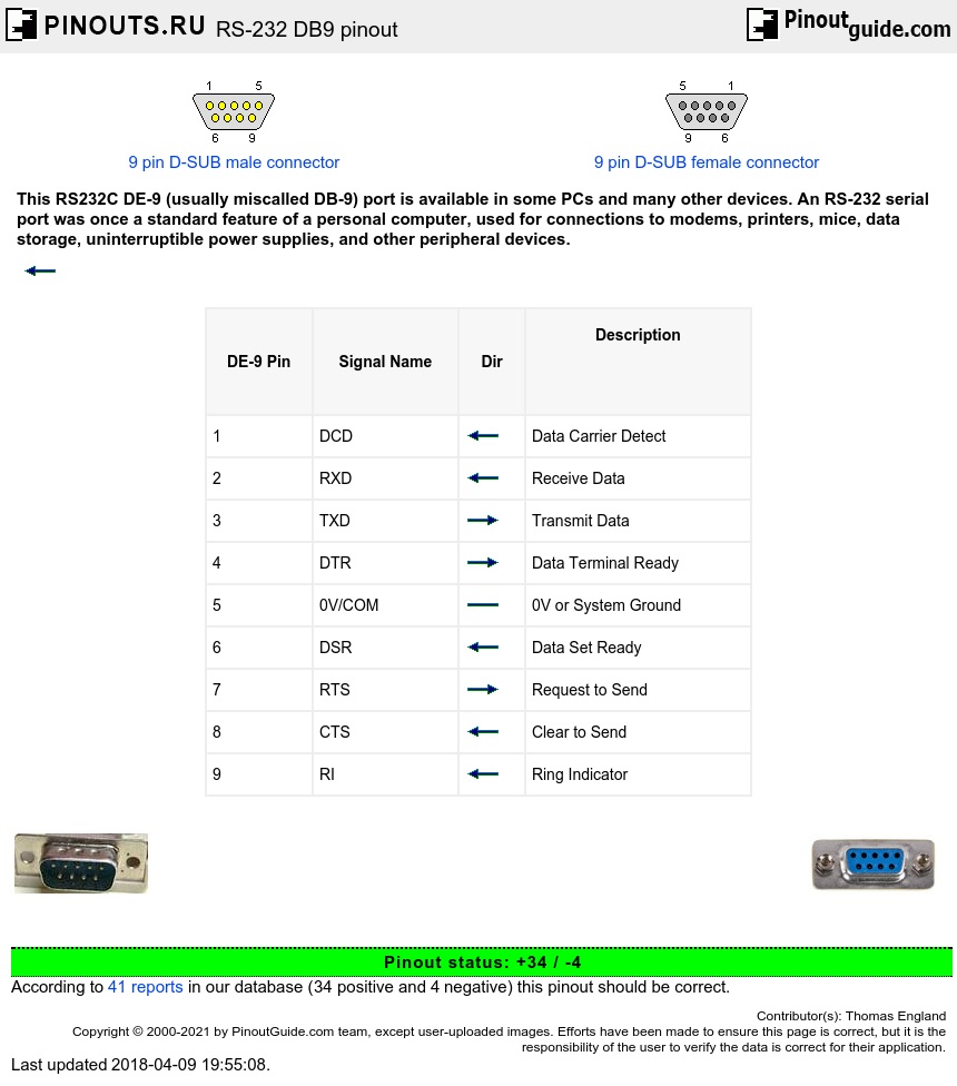
Pin 1: DCD ← Data Carrier Detect
Pin 2: RxD ← Receive Data
Pin 3: TxD → Transmit Data
Pin 4: DTR → Data Terminal Ready
Pin 5: 0V/COM − 0V or System Ground
Pin 6: DSR ← Data Set Ready
Pin 7: RTS → Request to Send
Pin 8: CTS ← Clear to Send
Pin 9: RI ← Ring Indicator
Voltage levels that represent the signals of RS232 serial port pinouts with respect to a system common (power/logic ground). The active state’s (SPACE) signal level is positive and the idle state’s (MARK) signal level is negative with respect to common. A communications protocol has to be specified by RS-232. Plus, RS-232 has multiple handshaking lines to use with modems (in most cases).
The RS-232 interface assumes that both DTE and DCE have similar electrical busses with identical grounds. Obviously, this assumption can be completely wrong when it comes to the long lines between the DTE and the DCE.
The maximum open-circuit voltage specified by the RS232 standard is 25 V, but normally signal levels 5 V, 10 V, 12 V, and 15 V.
According to the RS-232 standard, all data is bi-polar. For most equipment, an ON or 0-state (SPACE) condition is indicated by voltage from +3 V to +12 V and an OFF or 1-state (MARK) condition is indicated by voltage from -3 V to -12 V. However, some devices don’t recognize any negative levels and 0 V is enough for the OFF state. And sometimes smaller voltages can be enough to achieve the ON state. Thereby it’s possible to significantly reduce the overall range for RS-232 transmission/receiving.
Normal voltage for the output signal is from +12 V to -12 V. Also, there is a so-called “dead area” in a +3 V to -3 V range that is meant for line noise adsorption. In other serial port pinouts similar to RS-232 this range can be different (e.g. the V.10 definition has a +0.3 V to -0.3 V dead area). A whole lot of RS-232 receivers can easily sense differentials of 1 V, or even less.

There are no cable length limits defined directly by the RS-232 standard, so the main determining factor is the maximum capacitance tolerated by a compliant drive circuit. As a general rule, the critical length will be 15 m (or about 300 m provided that only low-capacitance cables were used). Frankly speaking, For longer distances, the RS-232 standard isn’t the best option for high-speed long-distance data transfer.
Keeping in mind that not all device manufacturers maintain the standard all the way through, it’s a good practice to study up on the documentation and to use a breakout box to test every new connection. In some cases, only the trial and error method can help to find the right cable to connect each pair of devices.
In compliance with the RS-232 standard, a DCE device must be connected to a DTE through the cable that has identical pin numbers in each connector (known as “straight cable”). Any cable/connector gender mismatches can be easily fixed with gender changers. Also, in common use are cables with a 25-pin D-sub connector on one end and a RS-232 9-pin connector on the other. Any equipment with 8P8C connectors is usually provided with a cable that has a DB-9 or a DB-25. Some even have interchangeable connectors for added flexibility.
If there’s no need to exploit the RS-232 to capacity, you can use a minimal 3-wire connection: transmit, receive, and ground. For a one-way data flow, there is a 2-wire option: data and ground. And for two-way hardware-controlled data transmission, the best alternative is a 5-wire version, that is the same as 3-wire but with the RTS and CTS lines added.
According to the RS-232 standard, data can be transmitted in lots of variations. The most common, however, is sending packets that include a 7-8 bit word, and a start, stop, and parity bits. As you can see on the diagram below, first comes the start bit (active low, +3 V to +15 V), then data bits, followed by the parity bit (if required by protocol), and finally the stop bit (used to bring logic high, -3 V to -15 V).

RS-232 compliant ports might not necessarily operate with several other serial signaling standards like RS-422, RS-423, RS-449, RS-422, 423, RS-485 and so on. For GPS receivers and depth finders using a TTL level close to +5 and 0 voltage, the mark level moves to an undefined area of the standard. You will need a current translator to use the RS-232 standard in an environment like this.
How they relate:
- RS-422 has a similar speed with RS-232 but differs in signaling
- RS-423 speed is the same without a balanced signaling
- Rs-449 decommissioned
MIL-STD-188 is similar to RS-232, but has a great rise time control with a better impedance. Thinking of ditching your RS-232 device? Not so fast! As you can see this serial protocol continues to defy all claims that it has been completely replaced by USB. Though modern communication systems require a more sophisticated system like the USB, we are going to continue using the standard serial ports.
Third-party applications have done well in enhancing the way we work with RS-232 serial port. An example is RS232 to Ethernet Connector developed by Electronic Team. You can find interesting usage scenarios in the User Guide .
Frequently Asked Questions
What does the rs in rs 232 stand for, does rs232 play any role in modern computers.
- serial port communication
RS232 serial cables pinout
RS232 serial connector pin assignment
- RS232 DB9 to DB25 converter
- RS232 serial loopback test plugs
RS232 null modem cables
- Spy / monitor cable
- Serial printer cables
- Yost RS232 on RJ45 standard
RS232 serial cable layout
Almost nothing in computer interfacing is more confusing than selecting the right RS232 serial cable. These pages are intended to provide information about the most common serial RS232 cables in normal computer use, or in more common language “How do I connect devices and computers using RS232?”
The RS232 connector was originally developed to use 25 pins. In this DB25 connector pinout provisions were made for a secondary serial RS232 communication channel. In practice, only one serial communication channel with accompanying handshaking is present. Only very few computers have been manufactured where both serial RS232 channels are implemented. Examples of this are the Sun SparcStation 10 and 20 models and the Dec Alpha Multia. Also on a number of Telebit modem models the secondary channel is present. It can be used to query the modem status while the modem is on-line and busy communicating. On personal computers, the smaller DB9 version is more commonly used today. The diagrams show the signals common to both connector types in black. The defined pins only present on the larger connector are shown in red. Note, that the protective ground is assigned to a pin at the large connector where the connector outside is used for that purpose with the DB9 connector version.
The pinout is also shown for the DEC modified modular jack. This type of connector has been used on systems built by Digital Equipment Corporation; in the early days one of the leaders in the mainframe world. Although this serial interface is differential (the receive and transmit have their own floating ground level which is not the case with regular RS232) it is possible to connect RS232 compatible devices with this interface because the voltage levels of the bit streams are in the same range. Where the definition of RS232 focused on the connection of DTE, data terminal equipment (computers, printers, etc.) with DCE, data communication equipment (modems), MMJ was primarily defined for the connection of two DTE’s directly.
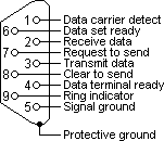
RS232 DB25 to DB9 converter
The original pinout for RS232 was developed for a 25 pins sub D connector. Since the introduction of the smaller serial port on the IBM-AT, 9 pins RS232 connectors are commonly used. In mixed applications, a 9 to 25 pins converter can be used to connect connectors of different sizes. As most of the computers are equipped with the DB9 serial port version, all wiring examples on this website will use that connector as a default. If you want to use the example with a DB25, simply replace the pin numbers of the connector according to the conversion table below.
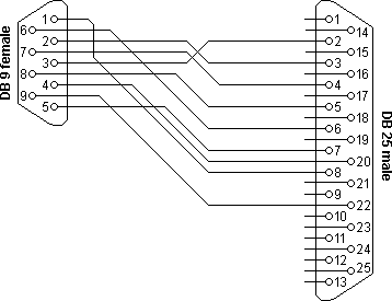
| DB9 | DB25 | Name | Function |
|---|---|---|---|
| 1 | 8 | Data carrier detect | |
| 2 | 3 | Receive data | |
| 3 | 2 | Transmit data | |
| 4 | 20 | Data terminal ready | |
| 5 | 7 | Signal ground | |
| 6 | 6 | Data set ready | |
| 7 | 4 | Request to send | |
| 8 | 5 | Clear to send | |
| 9 | 22 | Ring indicator |
RS232 serial loop-back test plugs
The following RS232 connectors can be used to test a serial port on your computer. The data and handshake lines have been linked. In this way all data will be sent back immediately. The PC controls its own handshaking. The first test plug can be used to check the function of the RS232 serial port with standard terminal software. The second version can be used to test the full functionality of the RS232 serial port with Norton Diagnostics or CheckIt.
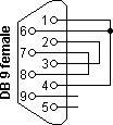
| DB9 | DB25 | Function |
|---|---|---|
| 1 + 4 + 6 | 6 + 8 + 20 | DTR ► CD + DSR |
| 2 + 3 | 2 + 3 | Tx ► Rx |
| 7 + 8 | 4 + 5 | RTS ► CTS |
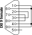
| DB9 | DB25 | Function |
|---|---|---|
| 1 + 4 + 6 + 9 | 6 + 8 + 20 + 22 | DTR ► CD + DSR + RI |
| 2 + 3 | 2 + 3 | Tx ► Rx |
| 7 + 8 | 4 + 5 | RTS ► CTS |
Testing occurs in a few steps. Data is sent on the Tx line and the received information on the Rx input is then compared with the original data.
The signal level on the DTR and RTS lines is also controlled by the test software and the attached inputs are read back in the software to see if these signal levels are properly returned. The second RS232 test plug has the advantage that the ring-indicator RI input line can also be tested. This input is used by modems to signal an incoming call to the attached computer.
The easiest way to connect two PC’s is using an RS232 null modem cable. The only problem is the large variety of RS232 null modem cables available. For simple connections, a three line RS232 cable connecting the signal ground and receive and transmit lines is sufficient. Depending of the software used, some sort of handshaking may however be necessary. Use the RS232 null modem selection table to find the right null modem cable for each purpose. For a Windows 95/98/ME Direct Cable Connection, the RS232 null modem cable with loop back handshaking is a good choice.
RS232 null modem cables with handshaking can be defined in numerous ways, with loop-back handshaking to each PC, or complete handshaking between the two systems. The most common null modem cable types are shown here.

| Connector 1 | Connector 2 | Function |
|---|---|---|
| 2 | 3 | Rx ◄ Tx |
| 3 | 2 | Tx ► Rx |
| 5 | 5 | Signal ground |

| Connector 1 | Connector 2 | Function |
|---|---|---|
| 2 | 3 | Rx ◄ Tx |
| 3 | 2 | Tx ► Rx |
| 5 | 5 | Signal ground |
| 1 + 4 + 6 | – | DTR ► CD + DSR |
| – | 1 + 4 + 6 | DTR ► CD + DSR |
| 7 + 8 | – | RTS ► CTS |
| – | 7 + 8 | RTS ► CTS |

| Connector 1 | Connector 2 | Function |
|---|---|---|
| 1 | 7 + 8 | RTS ► CTS + CD |
| 2 | 3 | Rx ◄ Tx |
| 3 | 2 | Tx ► Rx |
| 4 | 6 | DTR ► DSR |
| 5 | 5 | Signal ground |
| 6 | 4 | DSR ◄ DTR |
| 7 + 8 | 1 | RTS ► CTS + CD |

| Connector 1 | Connector 2 | Function |
|---|---|---|
| 2 | 3 | Rx ◄ Tx |
| 3 | 2 | Tx ► Rx |
| 4 | 6 | DTR ► DSR |
| 5 | 5 | Signal ground |
| 6 | 4 | DSR ◄ DTR |
| 7 | 8 | RTS ► CTS |
| 8 | 7 | CTS ◄ RTS |
Serial communication interface. RS232 pinout.
- What is the RS232 Protocol?
What does RS232 stand for?
- ❒ COM Port Pinout and Configuration
- RS232 cables
What is RS232 Protocol?
The RS232 protocol is a popular serial interface that is used to connect computers to peripheral devices such as modems. We will take a look at the serial port pinouts used to implement RS232 as well as some additional reference information concerning the protocol.
The RS232 protocol transmits data of wires employing signal levels that differ from the standard 5V in order to minimize signal interference. It performs asynchronous transmission at a constant rate that is synchronized with the start pulse signal’s level. Distances of up to 20 meters are the limit for reliable data transfer using the RS232 interface.
Data transfer standards are developed by the Electronic Industry Association (EIA). The prefix RS denotes a Recommended Standard, and all of the EIA standards begin with those characters. The formal specification of RS232 is that it is an interface which uses serial binary data exchange to communicate between DTE and DCE devices. DTE is the acronym for Data Terminal Equipment and DCE represents Data Communication Equipment. The basic example of these two types of equipment defines a computer as a DTE device with a modem filling the role of DCE.
Serial communication is implemented by the transmission of serial data between the DTE and DCE. For instance, a computer (DTE) might send the binary data “11011101” serially to the modem (DCE) which then replies by sending “11010101” back to the DTE device.
The RS232 protocol specifies the operation mode, electrical standards, number of bits, and voltage levels to be used when transferring data between a DTE and DCE.
Serial connectors
Serial communication devices make use of 9 or 25 pin D-type connectors for their cabled connections. They are commonly designated as DB-9 or DB-25 with the number used to differentiate between the pin counts. Various manufacturers’ names may replace the DB in the specifications. The plugs contain sockets and pins, with each pin numbered and labeled. A serial pinout diagram is presented below.
The RS232 protocol uses a 9 pin serial port that can have either male or female connectors. The most recent version of the protocol is known as RS232C.
RS232C retains the features of RS232 but uses 25 pins rather than a 9 pin serial pinout. Whether a DB9 serial pinout or a 25 pin connection is used, only three of the pins are required to connect terminal devices.
COM Port Pinout and Configuration
RS232 manages communication flowing between the DTE and DCE using serial pinouts of either the DB9 or DB25 variety. These D-sub connectors can terminate with an RS232 female pinout or DB25 or DB9 male connector pins. Each pin in a 9 or 25 serial connector pinout has its own distinct function. You can also learn RS485 pinout.

Functional Description:
In addition to defining electrical characteristics, RS232 specifies the signals used in serial cable pinouts and serial ports. Familiar items such as timing signals and ground are included in these specifications.
Following is a list of the signals used in an RS232 COM port pinout:
Protective Ground -This signal is connected to the chassis ground of the metallic connector.
Common Ground - Zero reference voltage level for all the control signals.
TxD (Transmit Pin) - To transmit data from DTE to DCE.
RxD (Receive Pin) - Sends data from DCE to DTE.
DTR (Data Terminal Ready) - DTE is ready to accept the request.
DCD (Data carrier Detect) - DCE accepts a carrier from a DTE located at a remote location.
DSR (Data Set Ready) - DCE is prepared to send and receive the information.
RI (Ring Indicator) - Detects the incoming ring tone on the telephone line.
RTS (Request to Send) - DTE call for DCE to send the data.
RTR (Ready to Receive) - DTE is geared up to receive data coming from DCE.
CTS (Clear To Send) - DCE is in a ready state to accept data coming from DTE.
These signals are the primary RS232 signals, but the protocol allows for secondary signals as well. They include secondary DTE, RTS, DCD, TxD, and RxD. The secondary signals are used to optionally connect DTE and DCE equipment.
RS-232 cables
Null modem connection.
Null modems enable serial communication between DTE and DCE devices. An RS232 null modem pinout links the Tx pin of a male connector with the Rx pin on an RS232 female and the Rx male’s pin to the female’s Tx pin.
Using the RS232 protocol you can connect two computers that do not have modems by using a null modem cable. This highlights one of the original uses of the RS232 protocol, which was developed in order to let teletype machines communicate with each other through their modems.

Straight-through cable
The other type of RS-232 Cable is the Straight-through cable. It is a one to one connector, It transmits a pin of one device that is connected to the transmit pin of another device and the receiver pin of one device is connected to the receiver pin of another device.

Conclusion:
Modern hardware designs use innovative serial communication protocols like USB, Ethernet, and Wi-Fi.
But still, RS232 has proven to be used. The reason is, RS232 signals spread over longer distances. Moreover, it has better noise immunity. It is proven to be compatible across different manufacturers for interfacing computer and modems.
- Serial Port Software
- What is Serial Port
- RS232 Pinout
RS232 Pinout, Definition, Uses, Speed & Baud Rate

RS232 is a standard for serial communication between devices. It is commonly used to connect computer equipment, although it can also be found in other electronic devices such as TVs and printers.
Table of Contents
What is the rs232 protocol.
It was introduced in the 1960s. Back then, RS232 was preferred for connecting computers and Programmable Logic Controllers (PLC) with peripherals such as printers, mice, and modems. But these are now being replaced with modern technologies like Universal Serial Bus (USB).
It is an asynchronous protocol, meaning that it does not require a clock signal to synchronize data transfer. The simplicity of the RS232 interface makes it widely used in a variety of applications including industrial control, barcode scanners, and GPS receivers. It is also commonly used in debugging tools such as JTAG adapters.
This protocol has dedicated cable and connector standards to support serial data exchange. Let’s know more about the connector and cable used for RS232.
RS232 connector
As you can see, it is large compared to the other connectors. The old version had 25 pins. This was later reduced to 9 pins which are being used currently.
RS232 cable
The cables provide the necessary electrical connection for the terminals during data transfer. Thus RS232 terminals should not be connected with ordinary cables.
Since the connection is between the DTE and DCE, the pins are assigned a 1:1 order. That means the Nth pin of DTE should be connected to the Nth pin of DCE. Thus, no crossover connection occurs in this protocol.
Speed and baud rate
Rs232 pinout.
RS232 protocol uses a 9-pin DB9 connector. The pinout of the male and female RS232 connectors is shown below.
| 1 | DCD | Data Carrier Direct |
| 2 | RxD | Receive Data |
| 3 | TxD | Transmit Data |
| 4 | DTR | Data Terminal Ready |
| 5 | GND | Ground |
| 6 | DSR | Data Set Ready |
| 7 | RTS | Request To Send |
| 8 | CTS | Clear To Send |
| 9 | RI | Ring Indicator |
These nine pins are divided into three categories:
Data pins – The flow of the data occurs through the data pins. Pins 2 and 3 are the data pins. These are RxD and TxD pins. The DTE and DCE have the interchanged order for data pins.
What is RS232 used for?
RS232 is mostly utilized in networks with PLCs where a PLC transfers data to other devices using this protocol. In this case, the PLCs act as DTE, and the other devices like printers, modems, etc act as DCE.
RS-232 requires a minimum of 3 wires for basic communication: transmit data, receive data, and ground.
Leave a Comment Cancel reply
Continue to site >>>

RS232 Connector
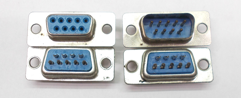
[Click the image to enlarge it]
RS232 connector is a port used for data exchange between equipments. It was designed for data exchange between DTE (Data Terminal Equipment) or PC and DCE (Data Communication Equipment) or MODEM. The need for RS232 came from limitations raised by parallel data exchange. RS232 uses serial communication protocol where data exchange is done bit by bit. Although RS232 is later replaced by faster USB (Universal Serial Bus); it is still popular in some areas. RS232 used to have 25 pin, now it is shrunk to just 9 pin.
RS232 Pin Configuration
New RS232 has nine pins as mentioned earlier. These nine pins are arranged in the port as shown in RS232 Connector Pinout . The DCE and DTE ports are exactly similar except for the direction of data flow. These nine pins are roughly divided in to three categories and we will discuss each category below.
|
|
|
|
|
| ||
| 2 | RXD | Receive Data (Data is received though this pin) |
| 3 | TXD | Transmit Data (Data is transmitted through this pin) |
|
| ||
| 1 | CD | Carrier Detect(Set by MODEM when answer is received by remote MODEM ) |
| 4 | DTR | Data Terminal Ready(Set by PC to prepare MODEM to be connected to telephone circuit) |
| 6 | DSR | Data Set Ready(Set by MODEM to tell PC it is ready to receive and send data) |
| 7 | RTS | Request To Send(Set by PC to tell MODEM that MODEM can begin sending data) |
| 8 | CTS | Clear To send(Set by MODEM to tell PC that it is ready to receive data) |
| 9 | RI | Set by MODEM to tell PC a ringing condition has been detected. |
|
| ||
| 5 | GND | Ground (Used as reference for all pin voltage pulses) |
RS232 Features and Specifications
- RS232 uses Asynchronous communication so no clock is shared between PC and MODEM.
- Logic ‘1’ on pin is stated by voltage of range ‘-15V to -3V’ and Logic ‘0’ on pin is stated by voltage of range ‘+3V to +15V’. The logic has wide voltage range giving convenience for user.
- MAX232 IC can be installed easily to establish RS232 interface with microcontrollers .
- Full duplex interface of RS232 is very convenient.
- Two pin simplex RS232 interface can also be established easily if required.
- A maximum data transfer speed of 19 Kbps(Kilobits per second) is possible through RS232
- A maximum current of 500mA can be drawn from pins of RS232
- The interface can be established up to a distance of 50 feet.
Disadvantages of RS232
- There is no pin dedicated for powering devices (No VCC)
- More communication pins
- Switching voltages between +15v and -15v is difficult at higher speeds
- A maximum speed of 19 Kbps
- A maximum distance of 50 feet
- More pins lead to higher noise
- Only a single device can be connected to RS232 connector unlike I2C
- Need hardware to convert high voltage logic of RS232 to be compatible to TTL (controller and processor units)
Where RS232 is Used?
A few examples where RS232 are suitable to use:
1. When you want a simple communication interface between two units. A two pin full duplex communication can be establishes easily on RS232 port.
2. RS232 is used in systems where clock sharing is difficult. RS232 is ASYNCHRONOUS so there will be no clock sharing between systems. All you need to do is set data bit rate for each unit. Once baud rate is set the units will sample the data according to set baud rate.
3. RS232 is also used to control a single unit specifically without delay or errors.
4. RS232 interface also delivers data with more accuracy which is a requirement in some cases.
How to use RS232 connector?
As mentioned before we cannot connect RS232 directly to controller we need MAX232 IC to covert high voltage signals to TTL and vice versa. A typical circuit for it is shown below.
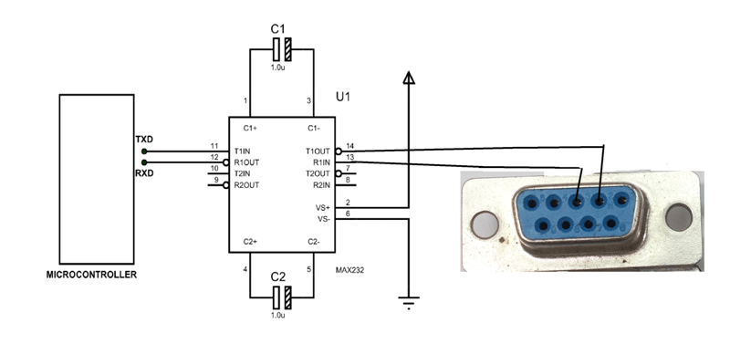
In here we are connecting controller to female RS232 through MAX232 converter chip. The communication voltages reach as high as +15V and as low as -15V in RS232. There voltage levels cannot be used in sensitive electronics so we use a mediator that is MAX232.
The chip coverts TTL logic pulses of controller to RS232 voltage level pulses and vice versa. Without this chip you may damage something permanently.
Applications
- Personal Computers
- Memory devices
- Motor control units
- Printers and Scanners
- Telephone lines
- Used basically where serial data transfer is required
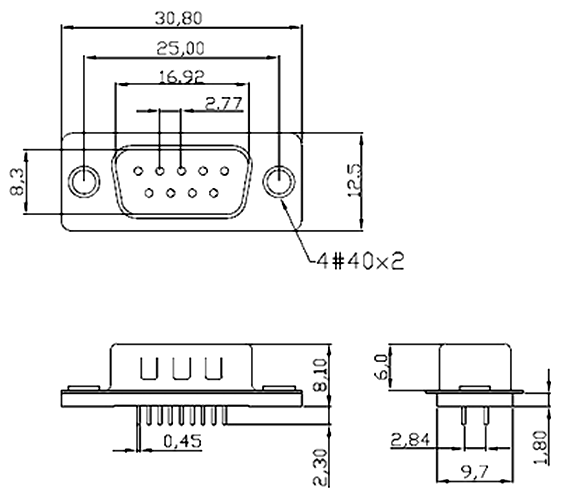
All parameters are in millimeters.
Related Post
Join 20k+subscribers.
We will never spam you.
Be a part of our ever growing community.

Amphenol RF's AUTOMATE Type A Mini-FAKRA quad-port jack is designed with a compact, modular housing

The ECX-31B tuning fork crystal brings efficiency to mobile, industrial and wireless applications.

200-300W ultra-compact medical external power supplies reduce volume by 50%

WAGO’s 2601 series super-compact, tool-free PCB terminal blocks with lever technology

1555F Series enclosures have several innovative features that provide excellent functionality
The EMC product range includes PCB and Cable ferrites, inductors, capacitors, and more...

General-purpose thick-film, anti-sulfur resistors designed for long-term performance and reliability

MAX40109 precision, single-flow calibration signal conditioning AFE for pressure sensor applications

Contact Info

ActiveXperts Serial Port Component
Add serial communication functionality to your Windows application. Samples included for Visual Studio .NET, C++, VBScript, Powershell and more.
ActiveXperts.com » Serial Port Component » Tutorials » RS232
RS232 Serial Port Connector Pin Layout
RS-232 is a serial communications standard that provides asynchronous and synchronous communication capabilities, such as hardware flow control, software flow control, and parity check. It has been widely used for decades. Almost all gears, instruments with digital control interface, and communications devices are equipped with the RS-232 interface. The typical transmission speed of an RS-232 connection is 9600 bps over a maximum distance of 15 meters.
The following document describes the functions of the pins on the RS232 9 and 25 pin Sub-D connectors used in serial communications. The pins in the images are as viewed from the pin side (not the solder or printed circuit board side). The male sockets are used on the DTE (Data Terminal Equipment ) or PC side. The female sockets are on the DCE (Data Communication Equipment ) or Modem Side.
Using the ActiveXperts Serial Port Component you can send and receive data and control the RS232 port.
RS232 9 Pin connector (DB-9)
| 1 | DCD | Data Carrier Detect |
| 2 | RD | Received Data |
| 3 | TD | Transmitted Data |
| 4 | DTR | Data Terminal Ready |
| 5 | GND | Signal Ground |
| 6 | DSR | Data Set Ready |
| 7 | RTS | Request To Send |
| 8 | CTS | Clear To Send |
| 9 | RI | Ring Indicator |
RS232 25 Pin connector (DB-25)
| 1 | PG | Protective Ground |
| 2 | TD | Transmitted Data |
| 3 | RD | Received Data |
| 4 | RTS | Request To Send |
| 5 | CTS | Clear To Send |
| 6 | DSR | Data Set Ready |
| 7 | SG | Signal Ground |
| 8 | CD | Carrier Detect |
| 9 | - | Reserved |
| 10 | - | Reserved |
| 11 | - | Unassigned |
| 12 | SCD | Secondary Carrier Detect |
| 13 | SCTS | Secondary Clear To Send |
| 14 | STD | Secondary Transmit Data |
| 15 | TC | Transmitter Clock |
| 16 | SRD | Secondary Received Data |
| 17 | RC | Receiver Clock |
| 18 | - | Unassigned |
| 19 | SRTS | Secondary Request To Send |
| 20 | DTR | Data Terminal Ready |
| 21 | SO | Signal Quality Detector |
| 22 | RI | Ring Indicator |
| 23 | DRS | Data Rate Selector |
| 24 | DRS | Data Rate Selector |
| 25 | - | Unassigned |

Fundamentals of RS232 Communication Protocol: Working Principle and Applications
In the world of computer communications, the RS232 serial communication protocol has played a crucial role for several decades. This tutorial aims to provide a comprehensive understanding of the basic principles, workings, and applications of the RS232 protocol. So, let’s dive in!
Table of Contents
Our other Electronics-related tutorials are:
- RS485 Communication Protocol: Basics, Working Principle & Application
- Fundamental of Flip-Flops
You may also like reading:
- How to interface Arduino with RS232 communication protocol
- How to interface esp32 with rs485 (Modbus) sensors with example code
- Multiple ESP32 Communication via RS485
- How to interface Arduino with RS485 (Modbus) protocol
- How to interface Modbus RTU (RS485) sensors with Arduino
Introduction
RS232, also known as Recommended Standard 232, is a widely used serial communication protocol that was introduced in the 1960s. It provides guidelines for the interchangeability and compatibility of devices in serial data communication. RS232 has played a crucial role in computer communications and has been widely adopted in various industries.
It has served as a cornerstone in computer communication, enabling reliable information exchange between computers, modems, and peripherals. The standard specifies the electrical voltage levels, signal timing, and connector pin assignments for serial communication. Despite the emergence of newer protocols, RS232 retains its significance in certain applications, thanks to its simplicity and widespread support.
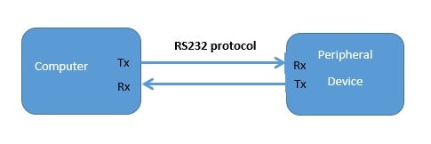
What is Serial Data Communication ?
Serial data communication is a method of transferring data between two devices or systems using a single data channel. It involves sending bits of data sequentially, one after the other, over a communication link. The data is transmitted in a continuous stream of bits, with a start bit and stop bit framing each unit of data, typically referred to as a “byte.”
This method is commonly used in various communication protocols, such as RS-232, UART, SPI, and I2C, to transmit data over long distances or between different types of devices. If serial data are synchronized with the clock signal it is called Synchronous serial data communication and if data are not synchronized with the clock signal it is called Asynchronous data communication.

What is the RS232 Protocol?
RS232 is a standard protocol that defines the electrical and functional characteristics of serial communication between devices. It uses a simple point-to-point connection, where data is sent in a sequential manner over a single wire.
RS232 operates on the principle of asynchronous communication, meaning that data is transmitted in individual bits without the need for a continuous clock signal. RS232 is able to communicate up to 15 meters at the rate of 1.492kbps without any interruption between two devices.
RS232 Protocol Applications
RS232, while less prevalent in modern technology, still has several practical applications. Here are some key points regarding its usage:
Industrial Automation: RS232 is commonly employed in industrial automation systems, enabling communication between devices like PLCs, HMIs, sensors, and actuators.
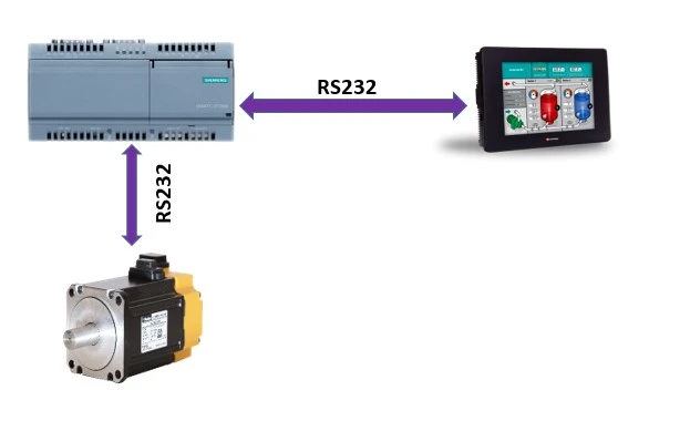
Legacy Systems: Many older systems and devices in various industries rely on RS232 for data exchange and control due to its compatibility and wide adoption.
Point-of-Sale (POS) Systems: RS232 is utilized in POS systems for connecting devices such as barcode scanners, cash registers, and receipt printers, ensuring seamless data transfer.

Telecommunications: RS232 finds use in telecommunications equipment like modems, routers, and switches, allowing configuration and management through a serial connection.

Medical Devices: RS232 is present in medical devices such as patient monitoring systems and diagnostic equipment, facilitating data transmission and control functionalities.
Embedded Systems: RS232 is popular in embedded systems and microcontroller-based projects, providing a simple means of programming and debugging.

How does the RS232 protocol work?
Consider a scenario where you have a computer (DTE – Data Terminal Equipment) connected to a modem (DCE – Data Communication Equipment) using an RS232 cable. The computer wants to send data to the modem for transmission over a telephone line.
The RTS (Ready to Send) signal is used by the Data Terminal Equipment (DTE) device, such as a computer, to inform the Data Communication Equipment (DCE) device, like a modem, that it is ready to transmit data. When the DTE is prepared to send data, it sets the RTS line to a logic high (1) level. The DCE receives this signal and acknowledges it by activating the Clear to Send (CTS) line.
The CTS (Clear to Send) signal is used by the DCE device to indicate that it is ready to receive data from the DTE device. When the DCE is prepared to receive data, it sets the CTS line to a logic high (1) level. The DTE receives this signal and can proceed with transmitting data.
The TXD (Transmit Data) line is used by the DTE to transmit data to the DCE. The DTE sends the binary data bits serially, one bit at a time, over the TXD line. The data is encoded and transmitted following the RS232 voltage levels and protocol.
For example: suppose we want to send 8 bits of information (11001110) to a computer (DTE) to a modem (DEC) then at first we make the RST of DTE to high. At this, DCE clears its CTS and informs DTA that DCE is ready to receive data from DTE. Sending data starts with a star bit that should be 0. After sending start bit data is transmitted by the TX line in this case the data is 11001110. A parity bit is sent after finishing to send data bits and it’s not mandatory to send. One or two bit of stop bit is sent to finish the transmission. Keep in mind that the stop bit should always be 1. Therefore, the total data packet will be 01100111011.

How RS232 protocol processes the data
Voltage levels.
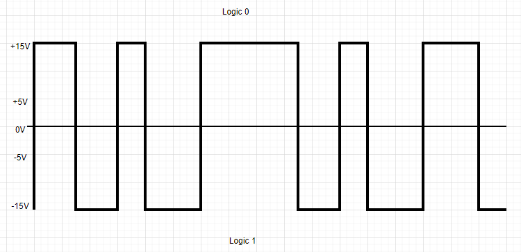
RS232 employs voltage levels to represent binary data. Traditionally, positive voltage represents logic 0 which ranges from +5V to +15V, while negative voltage represents logic 1 in the range of -5V to -15V. Logic 1 is referred to as “marking” and logic 0 is referred to as “spacing”. However, modern RS232 implementations often use inverted logic, where positive voltage represents logic 1, and negative voltage represents logic 0.
Data Encoding
To transmit data effectively, RS232 utilizes a method called data encoding. It converts the binary data into a format suitable for transmission over the serial connection. Commonly used encoding schemes include ASCII (American Standard Code for Information Interchange) and Unicode.
Start and Stop Bits
RS232 adds start and stop bits to each data byte transmitted. These bits provide synchronization and framing for the data. The start bit indicates the beginning of a data byte usually referred to as 0, while the stop bit marks its end. Typically, RS232 uses one start bit and one or two stop bits.
The parity bit is a basic error-checking mechanism used in data communication. It comes in four variations: even, odd, marked, and spaced. To illustrate, consider the number 011. In the case of even parity, the parity bit would be set to 0, while for odd parity, it would be set to 1.

The baud rate determines the speed at which data is transmitted over an RS232 connection. It represents the number of signal changes per second. Common baud rates for RS232 communication include 9600, 19200, and 115200 bits per second (bps). Higher baud rates allow for faster data transfer but may require more reliable cabling.
RS232 Cable
An RS232 cable, also known as a serial cable, is used to establish a connection between devices that follow the RS232 serial communication standard. This cable enables the transmission of data and control signals between devices such as computers, modems, printers, and other peripherals.

RS232 Connector Types
RS232 supports different connector types, including DB9 and DB25. The DB9 connector comprises nine pins, while the DB25 connector has 25 pins. These connectors ensure a secure and reliable physical connection between devices.
These cables are of two types one is Male connectors (DTE) and another one is female connectors (DCE). For example, DTE (Data transmission Equipment) cable is used for communicating between PC and modem, and DCE (Data communication Equipment) cable is used for communicating between modem and PLC or microcontroller.
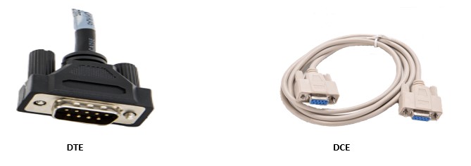
DB-9 Connector
The DB9 connector, also known as a DE-9 connector, is a common type of serial communication port. It features nine pins arranged in a compact rectangular shape. The DB9 connector is widely used for various applications, including connecting peripherals such as mice, keyboards, and printers to computers, as well as for serial communication (RS232) between devices like modems, routers, and industrial equipment. You can buy it from Amazon
DB-9 Connector Connection Diagram
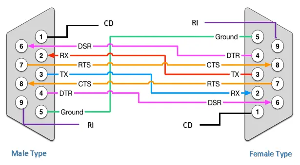
DB-9 Connector Pinout
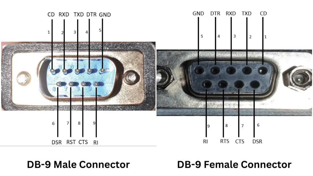
DB-9 connector pin definition
| 1 | Carrier Detect (CD) |
| 2 | Receive Data (RXD) |
| 3 | Transmit Data (TXD) |
| 4 | Data Terminal Ready (DTR) |
| 5 | Ground (GND) |
| 6 | Data Set Ready (DSR) |
| 7 | Request to Send (RTS) |
| 8 | Clear to Send (CTS) |
| 9 | Ring Indicator (RI) |
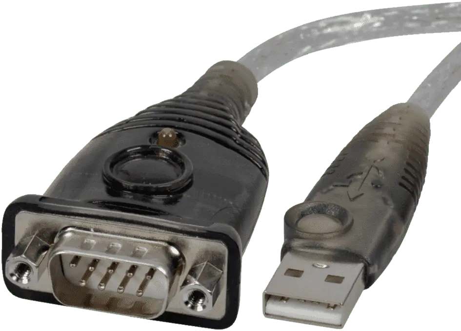
RS232 to USB cable
There are another three types of custom RS232 cables available in the market. The first one is RS232 to USB which helps you to communicate your PC to RS232 devices. This type of cable is also available in Amazon .
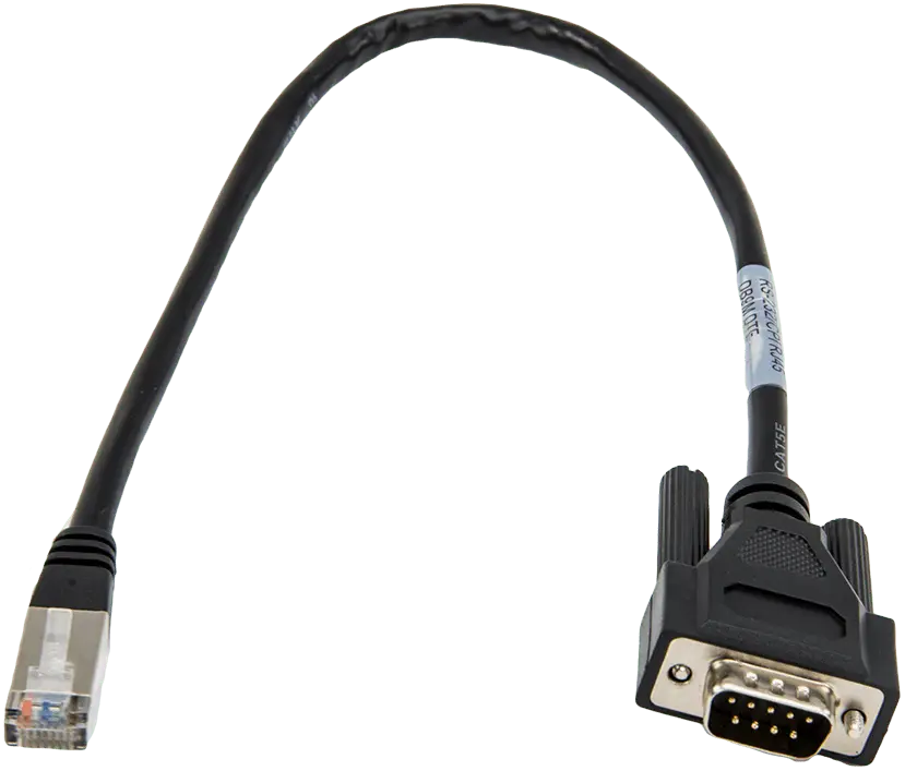
RS232 to Ethernet Cable
2 nd one is RS232 to Ethernet which also allows you to communicate your PC to RS232 devices. RS232 to Ethernet cable is also available in Amazon .
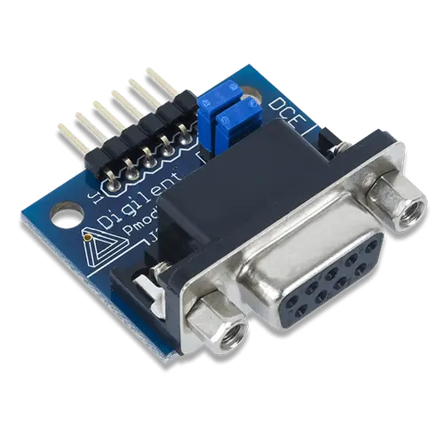
RS232 to UART module
And 3rd one is a module for communicating between the microcontroller and PC using RS232 protocol. This module is DCE (Data Communication Equipment) module and to communicate with PC you need DTE (Data transmission Equipment) for example, DB9.
Cable Length Limitations
An important consideration in RS232 communication is the limitations imposed by cable length. Due to voltage drop and signal degradation, RS232 cables are typically limited to a maximum length of 50 feet (15 meters). However, the use of signal amplifiers or converters can extend the reach of RS232 communication.
Limitations of RS232 Protocol
While RS232 has been widely used for serial communication, it also has certain limitations that have led to its declining popularity in recent years. Here are some of the limitations of RS232:
Limited Transmission Distance: RS232 communication is limited in terms of transmission distance. Typically, the maximum reliable distance for RS232 is around 50 feet (15 meters). Beyond this distance, signal degradation can occur, leading to errors in data transmission. This limitation makes RS232 less suitable for long-distance communication requirements.
Lower Data Transfer Rates: RS232 is a relatively slower communication protocol compared to modern alternatives such as USB, Ethernet, or wireless technologies. It is typically limited to lower data transfer rates, typically ranging from 19.2 kbps (kilobits per second) to 115.2 kbps. This limitation can be restrictive for applications that require high-speed data transmission.
Incompatibility with Modern Interfaces: RS232 interfaces are not directly compatible with many modern devices such as smartphones, tablets, and laptops, which often lack RS232 ports. This incompatibility makes it challenging to connect RS232 devices directly to these newer devices without additional adapters or converters.
Bulkiness and Cable Limitations: RS232 cables, especially those with DB9 or DB25 connectors, can be bulky and less flexible compared to modern cable types. The size and limitations of RS232 cables can restrict their use in compact or portable devices where space is a constraint.
Lack of Plug-and-Play Support: RS232 communication typically requires manual configuration and setup of communication parameters such as baud rate, parity, and stop bits. This lack of plug-and-play support can make initial setup and troubleshoot more complex compared to newer communication interfaces that offer automatic detection and configuration.
Despite these limitations, RS232 still finds utility in specific applications, especially in legacy systems, industrial automation, and scenarios where compatibility with existing RS232 devices is crucial. However, for many modern applications, alternative communication protocols with higher data rates, longer transmission distances, and more convenient interfaces have become preferred choices over RS232.
Rana Bhuiyan
I hold a B.Sc degree in Electrical & Electronic Engineering from Daffodil International University, Bangladesh. I am an Electronic circuit designer and Microcontroller programmer. I am interested in Robotics, Embedded System Design and IoT.
Recent Posts
Transistor: Definition, Working Principle, Types and Uses
What is a transistor? The transistor is a semiconductor device that acts like a switch in electronic circuits. A transistor can be turned OFF and ON as needed like a switch. Transistors are also...
Understanding the Basics of Logic Gates in Digital Systems
Logic gates serve as the fundamental components of all digital systems. These electronic circuits have one or more inputs and a single output, with the output determined by a specific logical...




COMMENTS
RS232 Connector Pin Assignment. RS232 Cable Information. DB 9 and DB 25 Connection. The original pin layout for RS232 was developed for a 25 pins D sub connector. In this pin-out provisions were made for a secondary communication channel. In practice, only one communication channel with accompanying handshaking is present.
Also, in common use are cables with a 25-pin D-sub connector on one end and a RS-232 9-pin connector on the other. Any equipment with 8P8C connectors is usually provided with a cable that has a DB-9 or a DB-25.
The pin diagram is an essential tool for technicians and engineers working with RS232 serial communication. It helps them correctly identify and connect the pins on the serial cable, ensuring proper data transmission between devices. Understanding the pin assignments and their functions is crucial for troubleshooting and configuring serial communication setups.
RS232 serial connector pin assignment The RS232 connector was originally developed to use 25 pins. In this DB25 connector pinout provisions were made for a secondary serial RS232 communication channel. In practice, only one serial communication channel with accompanying handshaking is present.
Pinout of RS-232 (EIA-232) serial interface and layout of 25 pin D-SUB male connector and 25 pin D-SUB female connectorRS-232 is the standard serial communications interface found on many types of equipment such as computers, modems, printers, Microcontrollers, eprom programmers, and a host of other devices. RS232 pinout may be varied.
RS232 manages communication flowing between the DTE and DCE using serial pinouts of either the DB9 or DB25 variety. These D-sub connectors can terminate with an RS232 female pinout or DB25 or DB9 male connector pins. Each pin in a 9 or 25 serial connector pinout has its own distinct function. You can also learn RS485 pinout.
RS232 cable The cables provide the necessary electrical connection for the terminals during data transfer. Thus RS232 terminals should not be connected with ordinary cables. The 9-pin DB9 cables are used to connect with the RS232 standard. Since the connection is between the DTE and DCE, the pins are assigned a 1:1 order.
RS232 Pin Configuration New RS232 has nine pins as mentioned earlier. These nine pins are arranged in the port as shown in RS232 Connector Pinout. The DCE and DTE ports are exactly similar except for the direction of data flow. These nine pins are roughly divided in to three categories and we will discuss each category below.
RS232 Serial Port Connector Pin Layout RS-232 is a serial communications standard that provides asynchronous and synchronous communication capabilities, such as hardware flow control, software flow control, and parity check.
The standard specifies the electrical voltage levels, signal timing, and connector pin assignments for serial communication. Despite the emergence of newer protocols, RS232 retains its significance in certain applications, thanks to its simplicity and widespread support.
RS232 Cable Information DB 9 and DB 25 Connection The original pin layout for RS232 was developed for a 25 pins D sub connector. In this pin-out provisions were made for a secondary communication channel. In practice, only one communication channel with accompanying handshaking is present.
RS-232 cables are a type of serial cable that uses the RS-232 standard. These cables have 25 pins. Unlike other types of data cabling, RS-232 is not used for video or audio signals. Instead, it is only used to transmit digital data such as binary code from one device to another. The most common usage of RS-232 cables is in configuration and control equipment, where it is often interfaced with ...
RS232 serial connector pin assignment. The RS232 connector was originally developed to use 25 pins. In this DB25 connector pinout provisions were made for a secondary serial RS232 communication channel. In practice, only one serial communication channel with accompanying handshaking is present.
RS-232. A DB-25 connector as described in the RS-232 standard. Data circuit-terminating equipment (DCE) and data terminal equipment (DTE) network. In telecommunications, RS-232 or Recommended Standard 232 [ 1] is a standard originally introduced in 1960 [ 2] for serial communication transmission of data. It formally defines signals connecting ...
Pinout of PC serial port (RS-232 DE9) and layout of 9 pin D-SUB male connector and 10 pin IDC male connectorThis RS232C DE-9 (usually miscalled DB-9) port is available in some PCs and many other devices. An RS-232 serial port was once a standard feature of a personal computer, used for connections to modems, printers, mice, data storage, uninterruptible power supplies, and other peripheral ...
This document provides a diagram and description of the pin assignments for a 9-pin RS232 connector cable. The cable uses a 9-pin SUB-D connector on each end and assigns signals like Transmit Data, Receive Data, Data Terminal Ready, Signal Ground, Data Set Ready, Request To Send, Clear To Send, and Ring Indicator to specific pins while keeping others unused.
1 I am having a problem creating a cable to connect with two devices. The first devisce is an Intellivue MP70 that I want to connect to the RS232 port using an RJ45 end. On the other side there should also be a RJ45 connection that should be connected to a Lantronix EDS-MD Server, and i can't figure out the pin assignment.
RS232 serial port monitoring hardware stands out for a number of reasons, including its 9 pin RS232 pinout. This pinout can make a world of difference for successful RS232 serial communications. Thus, it is important to understand how the 9 pin RS232 cable pinout can affect the flow of serial data between devices.
The document discusses various RS232 connector types, pin assignments, and cable configurations. It provides diagrams of DB9 and DB25 connectors showing the pin assignments for transmit, receive and handshake signals. It also describes null modem cables and cables for connecting devices like printers, monitors and loopback tests.
ViewSonic RS-232 serial port on the lower left side: Connector type: DB 9-Pin Female; Use of straight-through parallel cable for connection; Pin Assignment: Pin # Signal Remark Female DB 9-Pin 1 NC 2 TXD Output from Display 3 RXD Input to Display 4 NC 5 GND GND 6 NC 7 NC 8 NC 9 NC frame GND RS-232 Communication Setting ...
Borisoglebsky District ( Russian: Борисогле́бский райо́н) is an administrative [1] and municipal [7] district ( raion ), one of the seventeen in Yaroslavl Oblast, Russia. It is located in the center of the oblast. The area of the district is 1,750 square kilometers (680 sq mi). [2] Its administrative center is the urban locality (a work settlement) of Borisoglebsky. [1 ...
Yaroslavl Oblast is located in the north of the European part of Russia, in the center of the East European Plain. The length of the region from north to south is 270 km, from west to east - 220 km. It has an advantageous geographical location - close proximity to Moscow and St. Petersburg. The climate is moderately continental, with long cold ...
Real estate listings Yaroslavl Oblast. Houses, apartments, lands for sale Yaroslavl Oblast Rooms Property Size sqft sqft Floor Year Built Year established Conditions Excellent Good Average Bad Heating System Collective Individual Heating Combustibles Heating Combustibles Coal Electric Gas Oil Solar Orientations North East West South North-east North-west South-east South-west Views Sea River ...
Rostov (Russian: Росто́в, IPA: [rɐˈstof]) is a town in Yaroslavl Oblast, Russia, one of the oldest in the country and a tourist center of the Golden Ring. It is located on the shores of Lake Nero, 202 kilometers (126 mi) northeast of Moscow. Population: 30,406 ( 2021 Census); [ 8 ]31,792 ( 2010 Russian census); [ 3 ]34,141 ( 2002 ...